Do you have a question about the Electra DNG 100 and is the answer not in the manual?
Overview of the DC Inverter ducted split unit range and model compatibility.
Details high-tech features like DC compressor drive and system features like variable capacity.
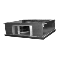
Describes the low-silhouette ducted indoor unit, its features, and installation options.
Covers the unit's pre-filters and their accessibility for maintenance.
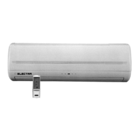
Explains the microprocessor controller and infrared remote control for operation.
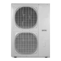
Details installation methods, construction, and fan features of the outdoor units.
Specifies flare type interconnecting tubing requirements and installation limits.
Lists available accessories such as remote controls and thermostats.
States that installation and operation manuals are included with each unit.
Provides a table matching outdoor and indoor units for different configurations.
Provides detailed technical specifications for the DNG 100 DCI indoor and OU12 4HP DCI outdoor units.
Provides detailed technical specifications for the DNG 125 DCI indoor and OU12 5HP DCI outdoor units.
Provides detailed technical specifications for the EMD 100 DCI indoor and OU12 4HP DCI outdoor units.
Provides detailed technical specifications for the EMD 125 DCI indoor and OU12 5HP DCI outdoor units.
Provides detailed technical specifications for the CD 140 DCI indoor and OU12 6HP DCI outdoor units.
Details the operating temperature and voltage limits for cooling and heating modes.
Shows the outline dimensions and key measurements for DNG 100 and DNG 125 indoor units.
Displays the outline dimensions and key measurements for the EMD 100 DCI indoor unit.
Displays the outline dimensions and key measurements for the EMD 125 DCI indoor unit.
Displays the outline dimensions and key measurements for the CD 140 DCI indoor unit.
Provides outline dimensions and key measurements for the OU12 DCI 4-5-6HP outdoor units.
Presents cooling and heating capacity data for the DNG 100 DCI unit.
Presents cooling and heating capacity data for the DNG 125 DCI unit.
Presents cooling and heating capacity data for the EMD 100 DCI unit.
Presents cooling and heating capacity data for the EMD 125 DCI unit.
Presents cooling and heating capacity data for the CD 140 DCI unit.
Provides correction factors for cooling and heating capacity based on tubing length.
Details pressure correction factors for cooling and heating based on total tubing length.
Demonstrates how to calculate corrected capacity and pressure using factors.
Shows airflow versus external static pressure for the DNG 100 DCI model.
Shows airflow versus external static pressure for the DNG 125 DCI model.
Displays airflow versus external static pressure for the EMD 100 DCI model.
Displays airflow versus external static pressure for the EMD 125 DCI model.
Illustrates airflow versus external static pressure for the CD 140 DCI model.
Lists air flow correction factors for DNG, EMD, and CD units at various nominal rates.
Illustrates the test setup for measuring indoor unit sound pressure levels.
Presents octave band sound pressure level spectra for DNG 100 and DNG 125 indoor units.
Depicts the test setup for measuring outdoor unit sound pressure levels.
Shows sound pressure level spectra for OU12 4HP DCI and OU12 5HP DCI outdoor units.
Details power supply, current ratings, circuit breaker, and wiring specifications for single-phase units.
Provides the wiring diagram for DNG 100 and DNG 125 DCI indoor units.
Offers the wiring diagram for EMD 100 and EMD 125 DCI indoor units.
Presents the wiring diagram for the CD 140 DCI indoor unit.
Shows the wiring diagram for OU12 4-5HP DCI outdoor units.
Displays the wiring diagram for the OU12 6HP DCI outdoor unit.
Illustrates the power supply connection to the outdoor unit for 1PH units.
Details separate power supply connections to outdoor and indoor units for 1PH units.
Provides refrigeration diagrams for heat pump models in cooling and heating modes.
Details tubing connections, torque specifications, and valve operation.
Defines common abbreviations used throughout the control system section.
Provides a block diagram and overview of the product's control system components.
Outlines rules for communication, temperature measurements, and system responses to failures.
Explains indoor fan control, load calculation, and heat mode operations.
Describes the default run mode, mode settings, ODU protections, and compressor speed control.
Details how to enter and exit technician test mode for system checks.
Describes the user interface, keys, menus, and status display for system monitoring.
Explains jumper settings for self-test, model selection, and presence detection.
Lists general and model-dependent system parameters for 4-5HP and 6HP units.
Provides crucial safety precautions and advisory notes for handling electrical assemblies.
Lists common system failures for indoor and outdoor units with probable causes and corrective actions.
Advises on checking system pressures and thermodynamic measures in technician mode.
Explains fault codes for outdoor and indoor units and their LED indication methods.
Details procedures for checking main electrical components like drivers, chocks, and capacitors.
Provides procedures for disassembling and servicing the outdoor unit components.
Details the steps for servicing the DNG indoor unit, including removing assemblies and parts.
Outlines the procedures for servicing the EMD indoor unit, covering assembly and part removal.
Explains the steps for servicing the CD indoor unit, including component removal.
Shows an exploded view of the DNG 100 and DNG 125 DCI indoor units.
Lists spare parts for the DNG 100 DCI indoor unit with part numbers and quantities.
Lists spare parts for the DNG 125 DCI indoor unit with part numbers and quantities.
Displays an exploded view of the EMD 100 DCI indoor unit.
Lists spare parts for the EMD 100 DCI indoor unit with part numbers and quantities.
Shows an exploded view of the EMD 125 DCI indoor unit.
Lists spare parts for the EMD 125 DCI indoor unit with part numbers and quantities.
Displays an exploded view of the CD 140 DCI indoor unit.
Lists spare parts for the CD 140 DCI indoor unit with part numbers and quantities.
Provides an exploded view of the OU12 4-5HP DCI outdoor unit.
Shows the general assembly of the OU12 4-5HP DCI outdoor unit.
Details the tubing assembly for the OU12 4-5HP DCI outdoor unit.
Illustrates the electronics assembly for the OU12 4-5HP DCI outdoor unit.
Lists spare parts for the OU12 4HP DCI outdoor unit with part numbers.
Lists spare parts for the OU12 5HP DCI outdoor unit with part numbers.
Provides an exploded view of the OU12 6HP DCI outdoor unit.
Shows the general assembly of the OU12 6HP DCI outdoor unit.
Details the tubing assembly for the OU12 6HP DCI outdoor unit.
Illustrates the electronics assembly for the OU12 6HP DCI outdoor unit.
Lists spare parts for the OU12 6HP DCI outdoor unit with part numbers.
Describes the RCW wall-mounted remote control for system operation.
Details the RCW2 wall-mounted remote control for advanced system management.
Explains the installation instructions for the base heater to prevent ice accumulation.
Provides installation instructions for the crank case heater to protect the compressor.
Details the installation instructions for the room thermostat for temperature sensing.
Lists references to installation and operation manuals for various unit models.