EasyManua.ls Logo

Electra GC 24 RC User Manual

Electra GC 24 RC
110 pages
To Next Page IconTo Next Page
Page #1 background imageLoading...
Page #1 background image
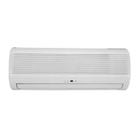
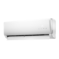
DELTA 18-21-24
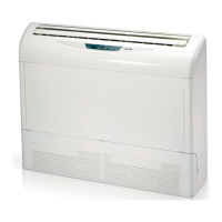
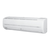
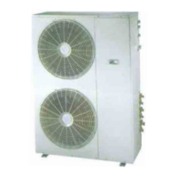
Indoor Units Outdoor Units
DELTA 18
GC 18
DELTA 21
GC 22
DELTA 24
OU7-24
OU7-24Z
Service Manual
SM DELTA 1-E.0 GB
JUNE – 2010
REFRIGERANT
R410A
HEAT PUMP
COOLING ONLY

Questions and Answers:

Electra GC 24 RC Specifications

General IconGeneral
BrandElectra
ModelGC 24 RC
CategoryAir Conditioner
LanguageEnglish

Summary

Introduction to DELTA Units

General Unit Overview

Details the DELTA split wall mounted models (ST and RC) and their features.

DELTA Series Main Features

Lists key technological innovations of the DELTA series, like R410A refrigerant and microprocessor control.

Indoor Unit Description

Describes the wall-mounted indoor unit and its included components.

Filtration System Details

Outlines the different types of air filters available for the DELTA series.

Control System Overview

Mentions the microprocessor controller and infrared remote control for operation and programming.

Outdoor Unit Specifications

Details the installation, features, and components of the DELTA outdoor units.

Accessories and Documentation

Lists optional accessories like ASK and RCW, and mentions inbox documentation.

Unit Matching Table

Presents a table showing compatible indoor and outdoor units for R410A refrigerant.

Product Data Sheets

DELTA 18 / GC 18 R410A Specifications

Provides detailed specifications for the DELTA 18 indoor unit and GC 18 outdoor unit with R410A.

DELTA 21 / GC 22 R410A Specifications

Lists specifications for the DELTA 21 indoor unit and GC 22 outdoor unit with R410A.

DELTA 24 / OU7-24 R410A Specifications

Details specifications for the DELTA 24 indoor unit and OU7-24 outdoor unit with R410A.

DELTA 24 / OU7-24Z R410A Specifications

Provides specifications for the DELTA 24 indoor unit and OU7-24Z outdoor unit with R410A.

DELTA 24 / OU7-24T R410A Specifications

Lists specifications for the DELTA 24 indoor unit and OU7-24T outdoor unit with R410A.

Rating Conditions and Operating Limits

Operating Limits for R410A

Defines the operating limits for cooling and heating modes, including voltage specifications.

Outline Dimensions

Indoor Unit Dimensions

Shows dimensional drawings and measurements for the DELTA 18, 21, 24 indoor units.

Outdoor Unit GC 18, 22 Dimensions

Presents dimensional drawings and measurements for the GC 18 and GC 22 outdoor units.

Outdoor Unit OU7-24, OU7-24Z Dimensions

Displays dimensional drawings and measurements for the OU7-24 and OU7-24Z outdoor units.

Performance Data and Pressure Curves

DELTA18 GC18 R410A Cooling Performance

Provides cooling performance data for DELTA 18/GC 18 at 7.5m tubing, with legend.

DELTA18 GC18 R410A Heating Performance

Offers heating performance data for DELTA 18/GC 18 at 7.5m tubing, with legend.

Capacity Correction Factor by Tubing Length

Details correction factors for cooling and heating based on tubing length.

Cooling Pressure Curves

Shows suction and discharge pressure graphs vs. outdoor temperature for cooling.

Heating Pressure Curves

Displays suction and discharge pressure graphs vs. outdoor temperature for heating.

DELTA21 GC21 R410A Cooling Performance

Provides cooling performance data for DELTA 21/GC 21 at 7.5m tubing, with legend.

DELTA21 GC21 R410A Heating Performance

Offers heating performance data for DELTA 21/GC 21 at 7.5m tubing, with legend.

Cooling Pressure Curves (DELTA21)

Shows suction and discharge pressure graphs vs. outdoor temperature for cooling.

Heating Pressure Curves (DELTA21)

Displays suction and discharge pressure graphs vs. outdoor temperature for heating.

DELTA24/OU7-24 Cooling Performance

Provides cooling performance data for DELTA 24/OU7-24 at 7.5m tubing, with legend.

DELTA24/OU7-24 Heating Performance

Offers heating performance data for DELTA 24/OU7-24 at 7.5m tubing, with legend.

Cooling Pressure Curves (DELTA24)

Shows suction and discharge pressure graphs vs. outdoor temperature for cooling.

Heating Pressure Curves (DELTA24)

Displays suction and discharge pressure graphs vs. outdoor temperature for heating.

Sound Level Characteristics

Sound Pressure Level Measurement

Describes how sound pressure level is measured, including a diagram.

Indoor Unit Sound Spectra

Presents octave band sound pressure level spectra for DELTA indoor units.

Outdoor Unit Sound Spectra

Shows octave band sound pressure level spectra for GC 18/22 outdoor units.

Outdoor Unit Sound Spectra (OU7)

Displays octave band sound pressure level spectra for OU7-24Z/OU7-24 outdoor units.

Electrical Data

Single Phase Unit Electrical Specs

Details power supply, current, circuit breaker, and wiring for single-phase units.

Wiring Diagrams

Indoor Unit Wiring Diagram

Shows the wiring diagram for DELTA 18, 21, and 24 indoor units.

Outdoor Unit GC 18 1PH Wiring Diagram

Presents the wiring diagram for the GC 18 1PH outdoor unit (Heat Pump Model).

Outdoor Unit GC 24 1PH Wiring Diagram

Shows the wiring diagram for the GC 24 1PH outdoor unit (Heat Pump Model).

Outdoor Unit OU7-24 1PH Wiring Diagram

Displays the wiring diagram for the OU7-24 1PH outdoor unit.

Outdoor Unit OU7-24 3PH Wiring Diagram

Presents the wiring diagram for the OU7-24 3PH outdoor unit.

Outdoor Unit OU7-24Z Wiring Diagram

Shows the wiring diagram for the OU7-24Z outdoor unit.

Electrical Connections

DELTA 18 / 21 1PH Electrical Connections

Illustrates electrical connections for DELTA 18/21 1PH indoor and outdoor units.

DELTA 24 1PH Electrical Connections

Shows electrical connections for DELTA 24 1PH indoor and outdoor units.

Refrigeration Diagrams

Heat Pump Models: DELTA 18 R410A Diagrams

Displays refrigeration diagrams for DELTA 18 in cooling and heating modes.

Heat Pump Models: DELTA 24 / OU7-24 Diagrams

Shows refrigeration diagrams for DELTA 24/OU7-24 in cooling and heating modes.

Heat Pump Models: DELTA 24 / OU7-24Z Diagrams

Displays refrigeration diagrams for DELTA 24/OU7-24Z in cooling and heating modes.

Cooling Only Models: DELTA 18, 21, 24 Diagrams

Presents refrigeration diagrams for DELTA 18, 21, 24 cooling-only models.

Tubing Connections

Control System

Electronic Control Overview

Introduces electronic control for service applications and lists model groups.

Controller Hardware and Display

Identifies components on the main PCB controller and the LED display.

System Operation and Fault Handling

Explains general functions, protections, and thermistor faults.

Cooling Mode Operations

Details cooling mode general functions, control functions, and cooling with autofan.

Heating Mode Operations

Covers heating mode general, IF rules, HE operation, and RC/SH group controls.

Automatic Mode Operations

Describes automatic cooling/heating general functions and RC/SH group controls.

Dry Mode Operation

Explains dry mode control function, COMP/IFAN operation, and notes.

Operational Protections

Details protections like defrost, high pressure, and deicing for various modes.

Timer Functionality

Details how the timer starts/stops operation, settings, and power failure effects.

Forced Operation Mode

Explains how forced operation allows starting/stopping at pre-set temperatures.

Sleep Mode Functions

Describes sleep mode activation, SPT adjustment, and time adjustment.

Air Filter Monitoring

Describes the filter LED indicator and how to reset the filter timer.

Controller Self-Test Procedure

Outlines the self-test flow chart by jumper or remote control settings.

On-Unit Indicators and Controls

Explains indicator functions and control buttons on the unit.

Clock Random Delay

Explains clock activation, interruption, and reset.

System Diagnostics

Details how to activate diagnostic mode and how problems are indicated by LEDs.

Troubleshooting Guide

Exploded Views and Spare Parts Lists

Indoor Unit: DELTA 18, 21, 24 Exploded View

Exploded view diagram for DELTA 18, 21, 24 indoor units.

Indoor Unit: DELTA 18, 21, 24 Parts List

Parts list for DELTA 18, 21, 24 indoor units.

Outdoor Unit: GC 18 ST Exploded View

Exploded view diagram for GC 18 ST outdoor unit.

Outdoor Unit: GC 18 ST Parts List

Parts list for GC 18 ST outdoor unit.

Outdoor Unit: GC 18 RC Exploded View

Exploded view diagram for GC 18 RC outdoor unit.

Outdoor Unit: GC 18 RC Parts List

Parts list for GC 18 RC outdoor unit.

Outdoor Unit: GC 21 RC Exploded View

Exploded view diagram for GC 21 RC outdoor unit.

Outdoor Unit: GC 21 RC Parts List

Parts list for GC 21 RC outdoor unit.

Outdoor Unit: GC 21 ST Exploded View

Exploded view diagram for GC 21 ST outdoor unit.

Outdoor Unit: GC 21 ST Parts List

Parts list for GC 21 ST outdoor unit.

Outdoor Unit: GCN 12 RC Exploded View

Exploded view diagram for GCN 12 RC outdoor unit.

Outdoor Unit: GC 24 ST Parts List

Parts list for GC 24 ST outdoor unit.

Outdoor Unit: GC 24 RC Exploded View

Exploded view diagram for GC 24 RC outdoor unit.

Outdoor Unit: GC 24 RC Parts List

Parts list for GC 24 RC outdoor unit.

Outdoor Unit: OU7-24 RC 1PH Exploded View

Exploded view diagram for OU7-24 RC 1PH outdoor unit.

Outdoor Unit: OU7-24 RC 1PH Parts List

Parts list for OU7-24 RC 1PH outdoor unit.

Outdoor Unit: OU7-24 ST 1PH Exploded View

Exploded view diagram for OU7-24 ST 1PH outdoor unit.

Outdoor Unit: OU7-24 ST 1PH Parts List

Parts list for OU7-24 ST 1PH outdoor unit.

Outdoor Unit: OU7-24Z RC/ST 1PH Exploded View

Exploded view diagram for OU7-24Z RC/ST 1PH outdoor unit.

Outdoor Unit: OU7-24Z RC/ST 1PH Parts List

Parts list for OU7-24Z RC/ST 1PH outdoor unit.

Outdoor Unit: OU7-24 RC 3PH Exploded View

Exploded view diagram for OU7-24 RC 3PH outdoor unit.

Outdoor Unit: OU7-24 RC 3PH Parts List

Parts list for OU7-24 RC 3PH outdoor unit.

Outdoor Unit: OU7-24 ST 3PH Exploded View

Exploded view diagram for OU7-24 ST 3PH outdoor unit.

Outdoor Unit: OU7-24 ST 3PH Parts List

Parts list for OU7-24 ST 3PH outdoor unit.

Optional Accessories

RCW Wall Mounted Remote Control

Describes the RCW wall-mounted remote control, its features, and ordering code.

RCW2 Wall Mounted Remote Control

Details the RCW2 wired controller, its capabilities, and ordering code.

A.S.K (All Season Kit)

Explains the ASK as a pressure regulator for low-temperature cooling.

Appendix A

Installation and Operation Manual DELTA 18, 21, 24

Refers to the separate installation and operation manual for DELTA 18, 21, 24 models.

Related product manuals