Do you have a question about the Electro-Voice AP3200 and is the answer not in the manual?
Details on connecting the amplifier to a 120V AC, 50/60 Hz power source.
Instructions for re-strapping the power transformer for 220/240V AC operation.
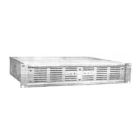
Guidance on installing the amplifier in a standard 19-inch equipment rack.
Ensuring adequate airflow and avoiding excessive temperatures for amplifier operation.
Details on making balanced and single-ended input connections.
Information on using XLR and barrier strip connectors for line outputs.
How to connect speakers using the four-terminal barrier strip.
Importance of speaker wire gauge for sound quality and power loss.
Method to calculate power loss in speaker cables for 8-ohm loads.
Method to calculate power loss in speaker cables for 4-ohm loads.
Understanding damping factor and its role in controlling speaker cone movement.
Equation to determine maximum cable length for a specified damping factor.
Guidance on selecting appropriate in-line fuses for speaker protection.
Using capacitors to protect compression drivers from low frequencies.
Independent protection for loads against transients, DC, and subsonic signals.
Details on the unique current-limiting and protection mechanisms.
Understanding the 'PROTECT' LED as a relative indicator of operating conditions.
Instructions for independent operation of each channel.
Instructions for operating the amplifier in bridged mono mode.
Introduction to trimpot adjustments for bias, current limit, and ripple cancellation.
List of essential test equipment required for proper calibration.
Procedure to minimize distortion caused by power supply ripple.
Procedure for setting the amplifier's bias point to minimize crossover distortion.
Steps to set negative and positive current limits for symmetrical clipping.
Procedure to verify the amplifier's behavior under short circuit conditions.
Information on how to order specific replacement components.
Guidelines for obtaining factory service or repairs.
Contact details for technical support and application assistance.
| Channels | 2 |
|---|---|
| Input Sensitivity | 1.4 V |
| Total Harmonic Distortion | < 0.1% |
| Signal-to-Noise Ratio | > 100 dB |
| Input Impedance | 20 kΩ balanced |
| Protection | DC, short circuit |
| Dimensions | 19" x 3.5" |
| Power Supply | 120V/240V, 50/60Hz |