Do you have a question about the Electro-Voice 7100 and is the answer not in the manual?
Details configuration for 120V AC power input.
Explains how to re-strap for 220/240V AC operation.
Provides instructions for mounting the amplifier in a standard 19-inch rack.
Outlines requirements for adequate airflow to prevent overheating.
Describes balanced and single-ended input connection methods.
Explains the use of XLR and 1/4" phone connectors for line output.
Details how to connect speakers to the binding post connectors.
Discusses the impact of speaker wire gauge on sound quality and power loss.
Explains the amplifier's damping factor and its influence on speaker cone control.
Describes independent load protection for each channel from transients and DC.
Details the unique current-limiting circuit for amplifier safety and reliability.
Explains the function and meaning of the 'PROTECT' LED indicator.
Instructions for operating the amplifier's channels independently.
Procedure for configuring and operating the amplifier in bridge mode.
Lists necessary tools and equipment for precise adjustment procedures.
Step-by-step guide for adjusting the bias trimpots for proper channel bias.
Provides information on how to order replacement components and part numbers.
Instructions for shipping the unit for authorized factory repair.
Contact information for application assistance and technical support.
| Brand | Electro-Voice |
|---|---|
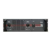
| Model | 7100 |
| Category | Amplifier |
| Language | English |