Do you have a question about the Electro-Voice TG5 and is the answer not in the manual?
Essential guidelines for safe operation and handling of the equipment.
Procedures and precautions for qualified personnel performing maintenance.
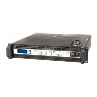
Welcomes users and introduces the TOUR GRADE SERIES power amplifiers.
Steps for unpacking, checking for damage, and verifying delivery contents.
Details the features and innovative technologies of the TOUR GRADE SERIES.
Warns about high power output and potential damage to connected loudspeakers.
Precautions regarding high output voltages at speaker connectors.
Information on FCC compliance and methods to correct radio frequency interference.
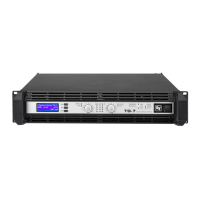
Identification and function of front panel elements on TG-5/TG-7.
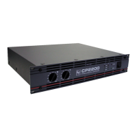
Identification and function of rear panel elements on TG-5/TG-7.
Default settings and power supply connection details.
Details power supply requirements and specifications for TG-5/TG-7.
Information on power consumption, heat generation, and ventilation needs.
Function of the mains switch and its soft-start circuit for safe power-on.
Instructions for front and rear mounting of the amplifier in a rack.
Guidelines for proper airflow, cooling, and groundlift switch usage.
Explains the function of the PARALLEL and BRIDGED LEDs.
Details the DUAL and PARALLEL audio input routing configurations.
Explains NORMAL and BRIDGED amplifier operation modes.
Describes options for input sensitivity and gain adjustments.
Procedures for balanced and unbalanced input signal connections.
Details on using output connectors for signal distribution.
How to connect loudspeakers in NORMAL mode using Speakon or terminals.
Specific cabling for Bi-Amp configuration in NORMAL mode.
How to connect loudspeakers in BRIDGED mode.
How to adjust channel volume levels using front panel controls.
Navigating and understanding information shown on the LC display.
Procedures for navigating the amplifier's menus and interpreting status displays.
Visual representation of the amplifier's CONFIG menu hierarchy.
How to set the delay before the amplifier powers up.
Setting the mains circuit breaker protection current.
Accessing service functions and setting the amplifier's name.
How to view and interpret recorded events in the log.
Details on event counters, history, and resetting the log.
Adjusting LCD contrast and brightness levels for optimal viewing.
Configuring the time interval before the display dims.
Selecting between Celsius (°C) and Fahrenheit (°F) for temperature display.
Restoring factory settings and viewing amplifier lifetime.
Accessing last log, module signature, and firmware version.
Steps to enter the MODULE CONFIG menu for RCM-26 settings.
Loading and managing presets for the RCM-26 module.
Setting CAN baud rate and selecting audio input sources.
Setting the amplifier's power state to On or Standby.
Meaning of PROTECT, MUTE, POWER, and STANDBY LEDs.
Interpretation of LED level indicators and the LIMIT LED function.
Monitoring CAN bus communication via the IRIS-Net LED.
Details on the fan cooling system and temperature monitoring.
How internal protections trigger messages and log events.
Benefits of True RMS measurement for mains network monitoring.
Adjusting circuit breaker emulation to prevent nuisance tripping.
Configuring power-on delay and soft-start for safe power-up sequences.
How the amplifier detects and responds to output short circuits.
The multi-stage ATP system for managing thermal conditions.
How ambient temperature affects cooling and potential standby mode.
The HF-Limiter's function in protecting output stages from high frequencies.
Introduction to the RCM-26 module for system control and monitoring.
Step-by-step instructions for installing the RCM-26 module.
Guide to switching RCM-26 between Pre and Post Fader modes.
Using IRIS-Net software for configuration and monitoring of RCM-26.
Details on AES/EBU connectors and their pin assignments.
Function of LOCK-LED and connecting to the REMOTE CAN BUS.
Setting network addresses and monitoring CAN bus activity with the STATUS LED.
Using control ports and the RS-232 interface for system integration.
RS-232 settings and fundamental CAN bus topology and termination rules.
Expanding CAN bus systems using repeaters and alternative topologies.
Illustrative examples of CAN bus network wiring configurations.
Specifications for CAN bus data transfer cabling and cable selection.
Detailed technical specifications for the TG-5 power amplifier.
Detailed technical specifications for the TG-7 power amplifier.
Overview of RCM-26 general features, audio inputs, and outputs.
Details on DSP functions, filters, and connectivity interfaces.
Summary of power, temperature, dimensions, and weight for RCM-26.
Visual representation of the amplifier's internal signal paths and components.
Detailed measurements of the amplifier's physical size.
Statement confirming compliance with relevant industry standards.
Contact details for Electro-Voice support and sales offices worldwide.
| Brand | Electro-Voice |
|---|---|
| Model | TG5 |
| Category | Amplifier |
| Language | English |