TOUR GRADE SERIES
18 Owner’s Manual
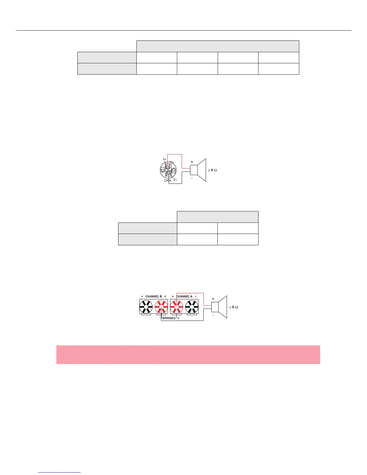
Output (Speakon-type Connectors / Terminals) in Bridged Mode
Setting the MODE switch on the power amp’s rear panel to BRIDGED lets the power amplifier run in
bridged mode operation and speaker connection has to be established using pins 1+ and 2+ of the
Speakon socket CH A, see illustration 2.16.
When using the speaker terminals in BRIDGED mode, the loudspeaker system has to be connected to the
red terminals of CHANNEL A and CHANNEL B. An illustration of how to correctly establish speaker
connection for this mode of operation is provided on the power amp’s enclosure.
Speakon CH A
Connection Pin 1+ 1- 2+ 2-
Channel Assignment A+ A- B+ B-
Table 2.6: Bi-Amp speaker connection in NORMAL operation mode, using only the Speakon A connector
Illustration 2.16: Speaker connection in BRIDGED operation mode, using Speakon A
Speakon CH A
Connection Pin 1+ 2+
Channel Assignment Bridged+ Bridged-
Table 2.7: Speaker connection in BRIDGED operation mode, using Speakon A
Illustration 2.17: Speaker connection in BRIDGED operation mode, using Terminals
CAUTION:
Due to the high current, using banana plugs for speaker connection is not permissible.