TOUR GRADE SERIES
Owner’s Manual 7
2 Installation
2.1 Controls, Indicators and Connections
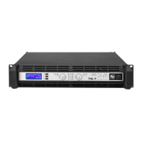
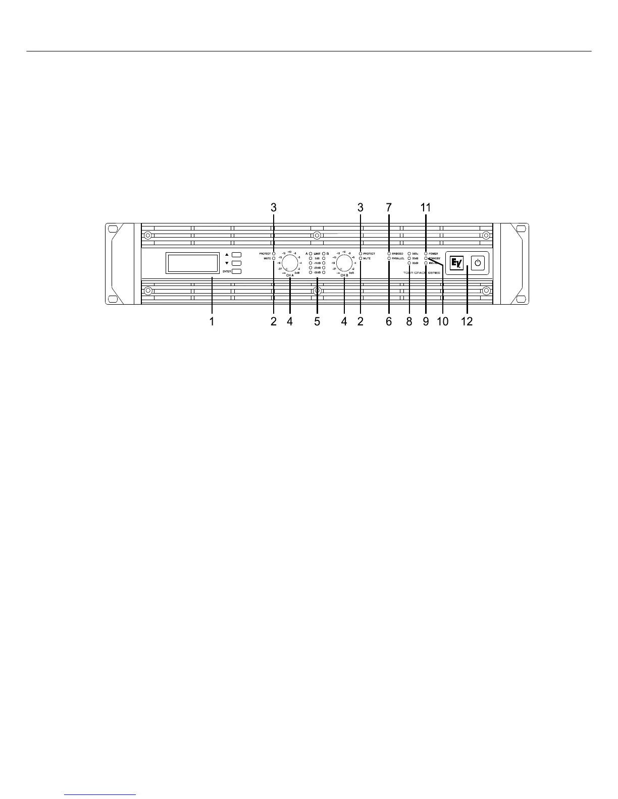
Front View
Illustration 2.1: TG-5/TG-7 front view
1
LC-Display (with controls)
2
Muting Indicator (MUTE) for channels A and B
3
Protections Indicator (PROTECT) for channels A and B
4
Input Level Control (CH A, CH B) for channels A and B
5
Level Indicators for channels A and B
6
Audio Input Mode Indicator (PARALLEL)
7
Power Amplifier Mode Indicator (BRIDGED)
8
Input Sensitivity/Gain Indicator (0dBu, 35dB, 32dB)
9
Remote Amplifier Indicator (IRIS-Net)
10
Standby Indicator (STANDBY)
11
Power On/Off Indicator (POWER)
12
Mains Switch