Instructions On How To Install NRS 90208 Extension Kits
• unplug the power amplifier from the mains
• detach all screws holding the cover plate of the appliance
• lift and remove the cover plate
• disconnect the flat-wire cable of the printed board assembly 81340/1
• detach all screws holding the printed board assembly 81340/1
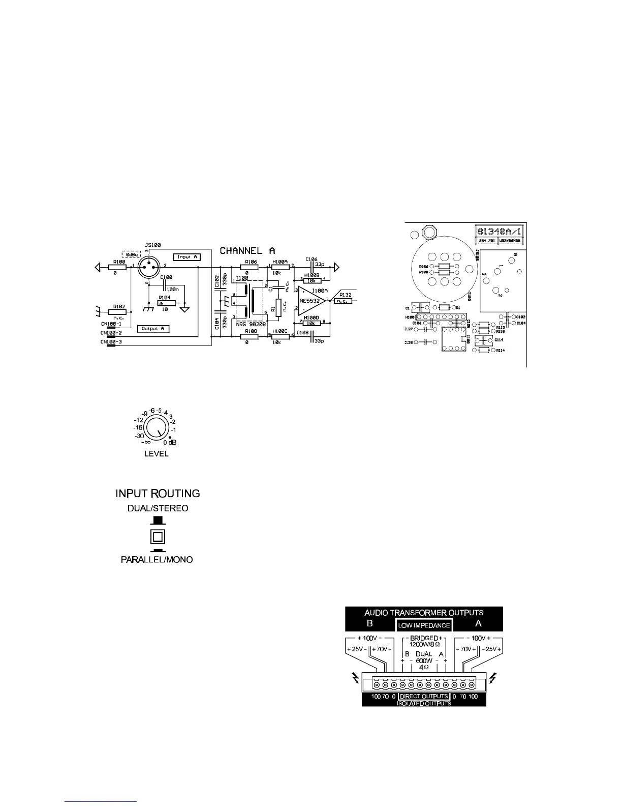
• remove the printed board assembly 81340/1 and unsolder the resistors R106 … R109
• attach insulators to the input transformers according to the corespondent marks on the printed board
assembly
• re-assemble the appliance by performing all steps described in the opposite order
Level Control
dB-scaled rotary controls for adjusting the power amplifier’s overall ampli-
fication. This control should be positioned between the 0 dB and the -6 dB
marks to prevent distortion in source devices. The labeling indicates the
actual attenuation applied to the internal specified factor of amplification.
Input Routing
If the switch is set to parallel/mono, the input connectors CHANNEL A and
CHANNEL B are electrically linked for direct parallel operation. With only
a single audio signal source connected, both channels are driven, while
their volume levels are still individually controlled via the level controls A
and B.
If the switch is set to its dual/stereo position, channels A and B are
separately amplified (two channel or stereo mode).
Power Outputs A&B
The loudspeaker cables are connected to the power
amplifier through high-performance binding posts –
with the necessary screw-plugs being supplied. For
connection purposes, it is possible to remove the 12-
pole terminal plug. Cables with 2.5 mm
2
or AWG 13
can be utilized. To provide flexible connections, all
floating output voltages – 25 V, 70 V, and 100 V
(ISOLATED OUTPUTS) – as well as the low-impedan-
ce output (DIRECT OUTPUTS) of both channels are
directly accessible.
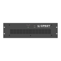
figure: power outputs of the CPS2T
figure: printed board assembly area channel A
– transformer retrofitting
figure: schematic of input channel A
6