REAR PANEL
6
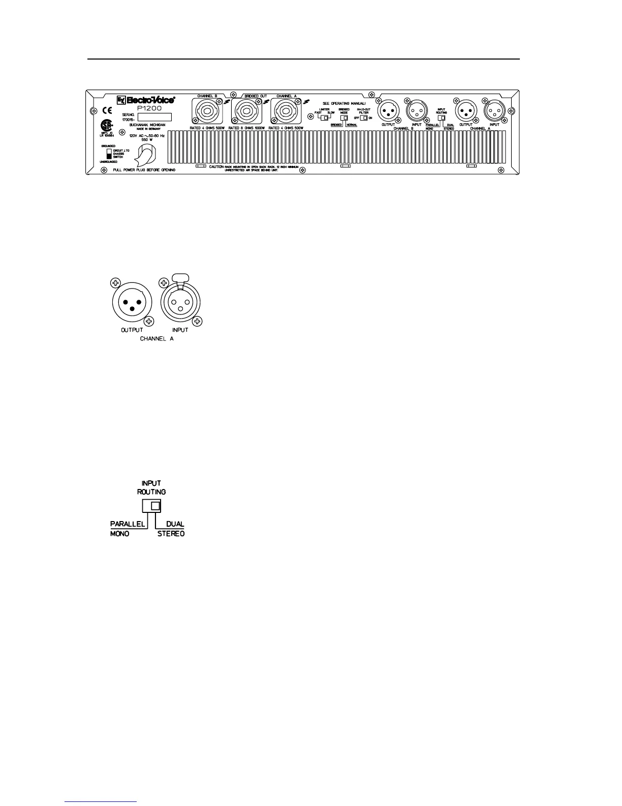
REAR SIDE
Power amplier input connectors
XLR connectors (male) are provided for “Looping” the signal to
other power ampliers. These are wired parallel to the XLR input
connectors in each channel.
The inputs of the power amplier are electronically balanced
and wired according to IEC 268. Isolation transformers can be
retrotted in order to avoid hum interference in larger sound
reinforcement systems. Please contact your dealer if you have
any problems.
Input wiring XLR
PIN 1: SHIELD
PIN 2: a, +, hot
PIN 3: b, -, cold
The inputs are electronically balanced.
The input sensitivity is set to 0dBu (775 mV) by the factory.
Please contact your local dealer if you want to change to 6dBu or
26 dB gain.
INPUT ROUTING
PARALLEL MONO
If the mode selector is in position PARALLEL MONO, the input
connectors channel A und B are directly wired in parallel, but the
volume for channel A or B can be adjusted independently using
the input controls A or B.
DUAL STEREO
If the mode selector is in position DUAL STEREO, channel A and
B are amplied separately.
Many mixing consoles have XLR connectors in the outputs, but are wired in such
a way that they are unbalanced. If a mixer is used with unbalanced outputs, PIN
1 and PIN 3 of the power amplier’s input connectors must be connected by a
jumper or PIN 3 must not be connected to the connection cable.
If signals are taken from unbalanced units via PIN 3 (b, -, cold) and PIN 2 (a, +, hot),
strange hum interference or high frequency oscillations can occur. These effects
can cause power ampliers or loudspeakers to malfunction.
 Loading...