11
IMTP(D) 2.2 – ITTP(D) 2.2/4.0/5.5/7.5 - ELECTROIL
ENG
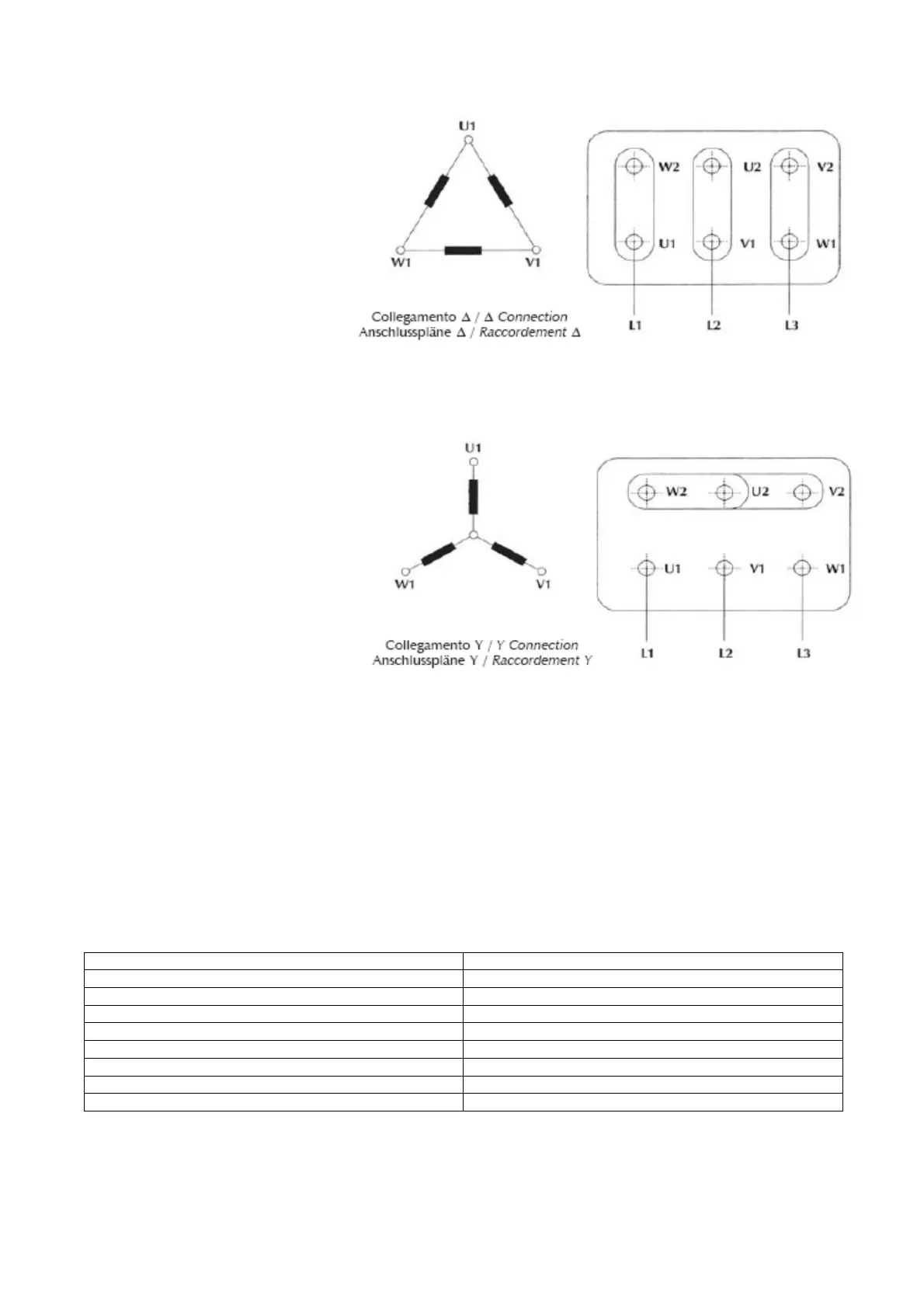
5.5 Motor-pumps phases connection
The single-phase inverter IMTP(D)2.2
must be installed on asynchronous
three-phase motor with 100-240Vac
50/60 Hz voltage supply. Phases
must be configured to delta mode if
the motor is 230V ∆ / 400V λ (most
common case, as in Figure 10).
Connect the N°3 motor terminals to
the U, V, W inverter output
connectors (fig. 13).
Figure 10 – Delta motor phases connection
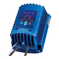
The three-phase inverters ITTP(D)2.2
and ITTP(D) 4.0/5.5/7.5 must be
installed on asynchronous three-phase
motor with 200-460 Vac 50/60 Hz
voltage supply. The phases must be
connected in star mode if the motor is
230V ∆ / 400 V λ (most common case,
as in Fig 11).
Connect the N°3 motor terminals to the
U, V, W inverter output connectors (fig.
14,16).
Figure 11 – Star motor phases connection
The inverter have an output over-current protection; it is not necessary to install any additional safety device between
the inverter and the pump in order to protect the motor in case of failure.
5.6 Electric connection to Line and Motor
Supply for IMTP(D)2.2 device is a single-phase voltage 100-240Vac, 50/60Hz.
Supply for ITTP(D)2.2 and ITTP(D)4.0/5.5/7.5 device is a three-phase voltage 200-460Vac, 50/60Hz.
The plant to which the inverter is connected must be conforms to safety regulations in use:
• Differential automatic switch: I ∆ n = 30mA
• Magnetic-thermal automatic switch with intervention current proportionate to the power of
the pump installed (see Table 1)
• Ground connection with total resistance less than 100 Ω
Table 2: Magnetic-Thermal protection
To make electrical connections observe the following instructions (reference to Figure from 12 to 16):