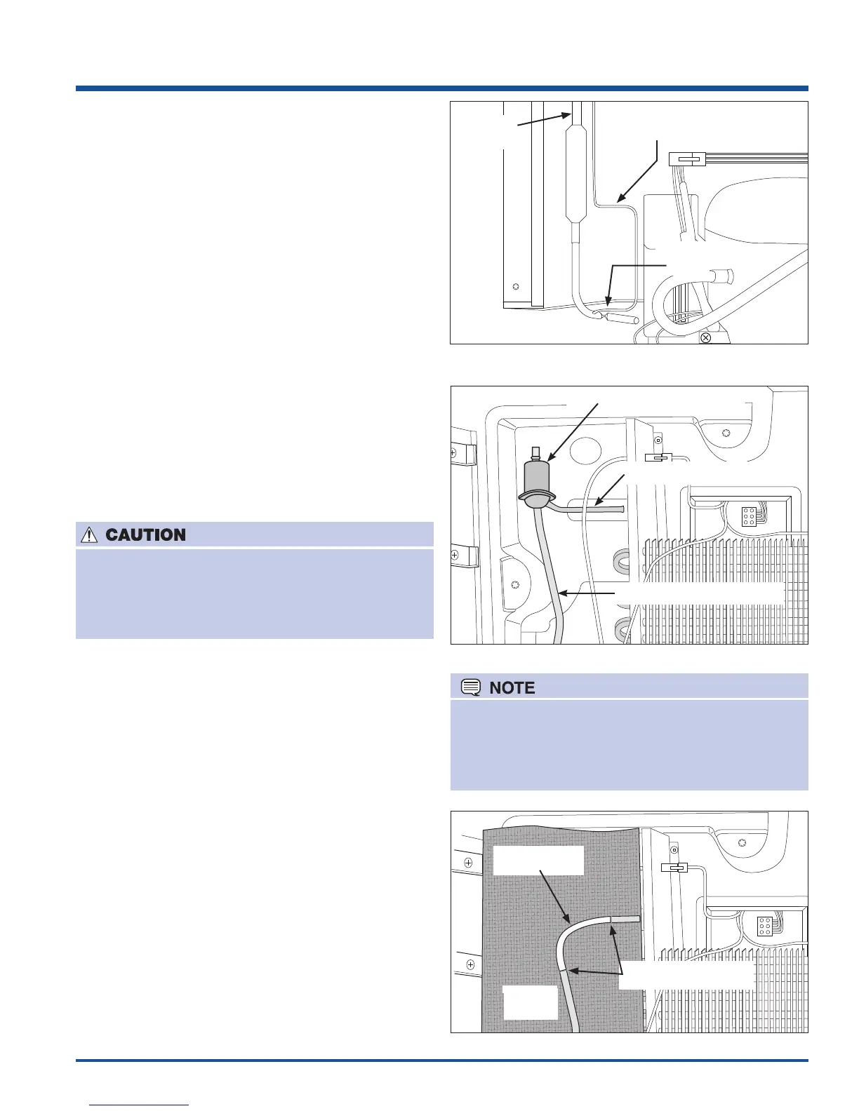
7-17
Sealed System
Capillary Tube
French Door Bottom Freezer Refrigerators Series
55 and 70 will feature a pressure regulator.
Series 56 and 71 will not have a pressure
regulator as shown in figure 7-16.
Pressure Regulator Removal
To replace the ice maker pressure regulator:
1. Disconnect refrigerator from electrical supply.
2. Remove freezer door, baskets and evaporator
cover.
4. Disconnect defrost heater and push it down out of
your way.
5. Cut ice maker suction line going into and out of the
regulator at line weld and remove regulator.
(See Figure 7-16 )
6. Clean both ends in suction line.
7. Place heat shield in freezer behind lines that were
connected to the cut out regulator. (See Figure 7-17)
8. Install the jumper tube in place of the regulator.
9. Weld the inlet and outlet lines to the jumper tube.
10. Replace filter-drier using caution to connect cap
tubes properly.
11. Evacuate and recharge system.
12. Run product to make sure refrigerant is circulating.
13. Reinstall evaporator and compartment covers.
Replace freezer baskets and door.
The regulator is no longer used in production. If it
fails in the field, it is to be replaced with a jumper
tube Part# 242036701 to connect ice maker suction
line to line going to accumulator on the evaporator.
Figure 7-16.
Pressure Regulator
Pressure Regulator Inlet Line
Outlet Line To Accumulator
Figure 7-17.
Heat
Shield
Jumper Tube
Weld Jumper Tube
4. Using a 3 cornered file, score a groove around
capillary tubes as close to old filter-drier as possible.
Break capillary tubes along score mark from filter-
drier.
5. Cut condenser outlet tube at filter-drier. Discard
filter-drier.
6. Thoroughly clean condenser outlet tube and
capillary tube.
7. Place inlet connection of filter-drier over condenser
tube approximately ¼” and solder.
8. Insert capillary tubes input end into filter-drier
outlets. (See Figure 7-12,13 and 14) Do not allow
tube to bottom against screen. Solder carefully so
that solder does not plug capillary tube.
9. Install process tube adapter to filter-drier.
10. Evacuate and charge system using recommended
procedure described under Evacuating and
Recharging.
11. Reassemble unit.
Figure 7-15.
Cut
Here
Cut
Here



 To Next Page