2010 dmm 49/96 599 73 68-54
11 ELECTRICAL COMPONENTS
• When replacing any of the components, please refer to the code shown in the
list of spare parts relating to the appliance being repaired.
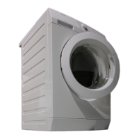
11.1 Anti-disturbance filter
11.1.1 General characteristics
This device is connected to the electricity power line input of the appliance and avoids the emission of radio
frequency disturbance in the electricity mains. It is incorporated into the main board.
1. Main circuit board
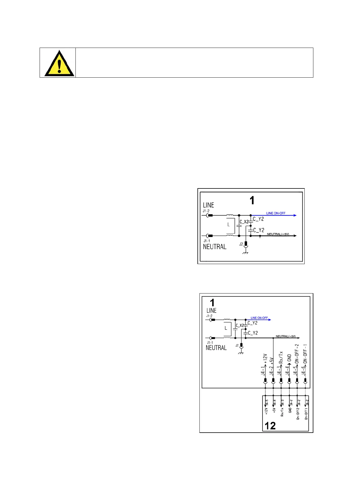
11.2 Display board
The main circuit board (1) supplies the power supply voltage to
the control/display board (12).
Turn the selector dial to select the programmes, press the
buttons to choose the options and press the START/PAUSE
button to start or pause the appliance.
The buzzer - where featured - is powered by the display board.
1. Main circuit board
12. Display board
 Loading...