2010 dmm 59/96 599 73 68-54
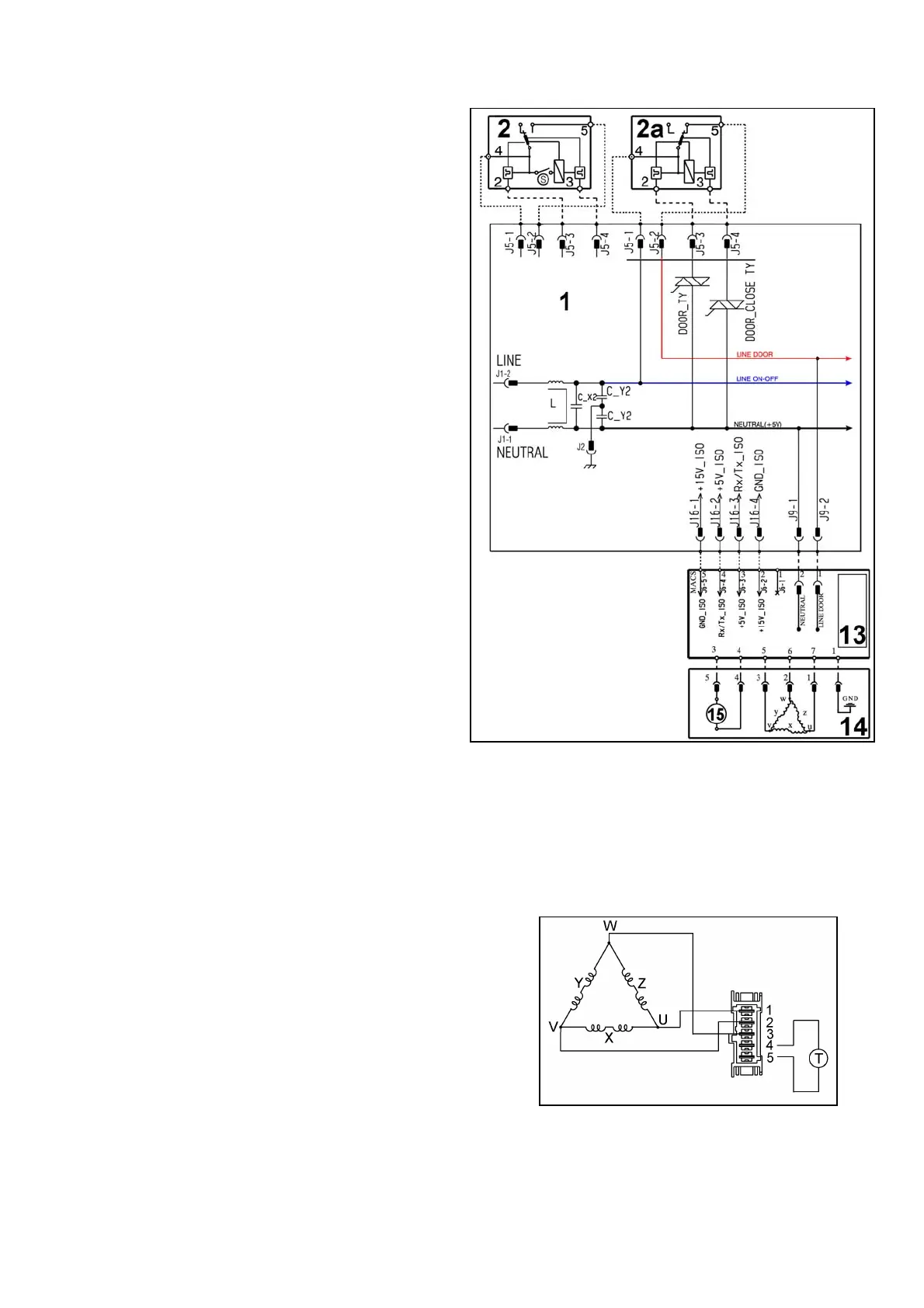
11.10 Three-phase asynchronous motor - Inverter
11.10.1 General characteristics
1. Main circuit board
2. Door safety interlock (with light micro-switch)
2a Door safety interlock (without light micro-switch)
13. Inverter
14. Motor
15. Tachometric generator
X-Y-X = Motor windings
11.10.2 Power supply to motor
Three-phase power is fed by the inverter (13), which sends through the connectors 5-6-7 the three phases to
connectors 1-2-3 on the motor (nodes U-W-V), where the windings (Y-X-Z-) are connected.
The phase shift between the phases is 120° and peak amplitude is 310 V.
It is possible to get an idea of the efficiency of the
motor by measuring the resistance of the coils:
Coil y ohm 5.8
∼ ±7% (contacts 2-3)
Coil x ohm 5.8
∼ ±7% (contacts 1-2)
Coil z ohm 5.8
∼ ±7% (contacts 1-3)
Coil T (tachometric) ohm 181.5
∼ ±7% (contacts 4-5).




 To Next Page