_-_, _
Rotate
_ FanBladeOpenings
1800
Changethe position of wire to left sidehole
(B) (A)
Figure 9B
FanW=re _
iii,i,i,i
(c)
1.
2.
3.
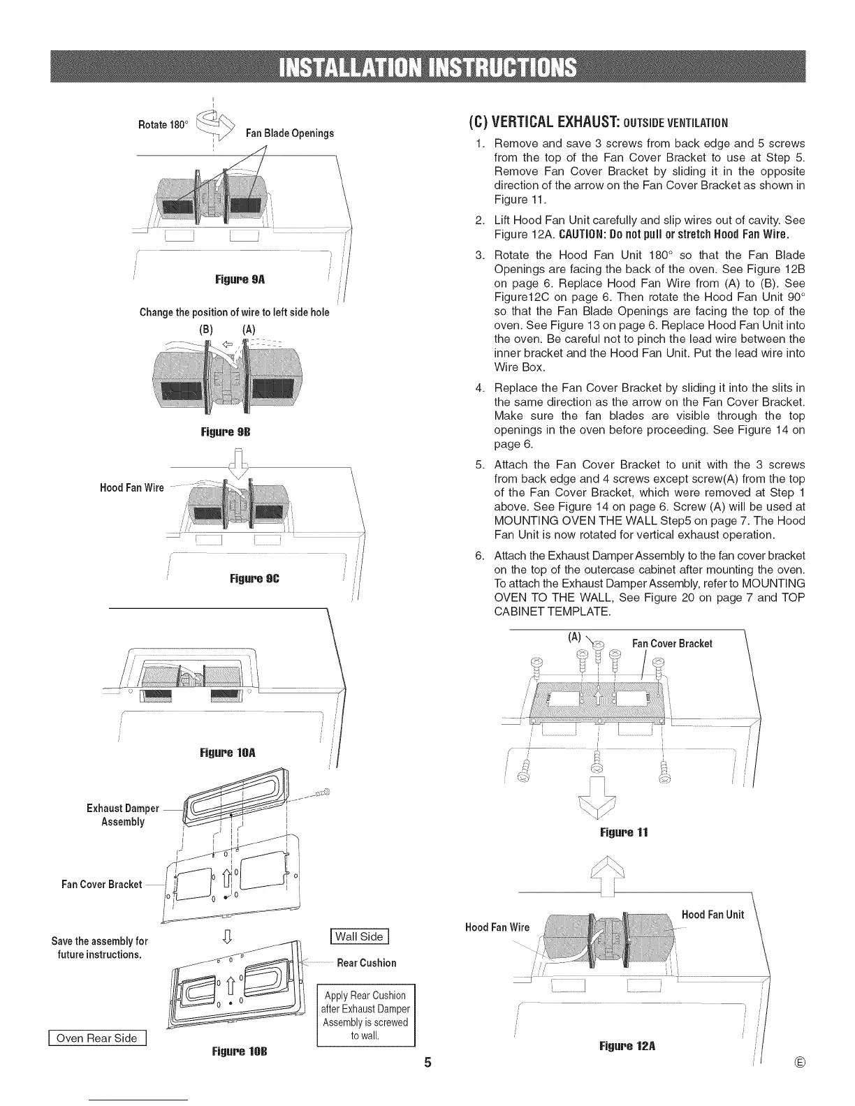
VERTICALEXHAUST:OUTSIDEVENTiLATiON
Remove and save 3 screws from back edge and 5 screws
from the top of the Fan Cover Bracket to use at Step 5.
Remove Fan Cover Bracket by sliding it in the opposite
direction of the arrow on the Fan Cover Bracket as shown in
Figure 11.
Lift Hood Fan Unit carefully and slip wires out of cavity. See
Figure 12A. CAUTION: Do not pull or stretch Hood Fan Wire.
Rotate the Hood Fan Unit 180 ° so that the Fan Blade
Openings are facing the back of the oven. See Figure 12B
on page 6. Replace Hood Fan Wire from (A) to (B). See
Figure12C on page 6. Then rotate the Hood Fan Unit 90 °
so that the Fan Blade Openings are facing the top of the
oven. See Figure 13 on page 6. Replace Hood Fan Unit into
the oven. Be careful not to pinch the lead wire between the
inner bracket and the Hood Fan Unit. Put the lead wire into
Wire Box.
4. Replace the Fan Cover Bracket by sliding it into the slits in
the same direction as the arrow on the Fan Cover Bracket.
Make sure the fan blades are visible through the top
openings in the oven before proceeding. See Figure 14 on
page 6.
5. Attach the Fan Cover Bracket to unit with the 3 screws
from back edge and 4 screws except screw(A) from the top
of the Fan Cover Bracket, which were removed at Step 1
above. See Figure 14 on page 6. Screw (A) will be used at
MOUNTING OVEN THE WALL Step5 on page 7. The Hood
Fan Unit is now rotated for vertical exhaust operation.
6. Attach the Exhaust DamperAssembly to the fan cover bracket
on the top of the outercase cabinet after mounting the oven.
To attach the Exhaust Damper Assembly, refer to MOUNTING
OVEN TO THE WALL, See Figure 20 on page 7 and TOP
CABIN ET TEM PLATE.
(A)
FanCover Bracket
Exhaust Dam
Assembly
FanCover Bracket
Savethe assemblyfor
future instructions.
I Oven Rear Side I
"_ _1 I Wall Side I
nlFJ_ __ .......................RearCushion
0 0 l --
, earOushio
!71I after ExhaustDamper
....... Assemblyisscrewed
towall.
Figure lOB
Figure 11
®