i
i
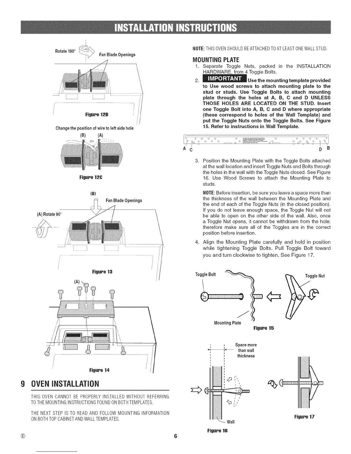
Rotate 180° _ FanBiadeOpenings
Changethe positionof wiretoleftside hole
(B) (A)
Figure 12C
(A) Rotate 900
{B)
FanBladeOpenings
NOTE:THISOVENSHOULDBEATTACHEDTOATLEASTONEWALLSTUD.
MOUNTING PLATE
1. Separate Toggle Nuts, packed in the INSTALLATION
HARDWARE, from 4 Toggle Bolts.
2. _ Use the mounting template provided
to Use wood screws to attach mounting plate to the
stud or studs. Use Toggle Bolts to attach mounting
plate through the holes at A, B, C and D UNLESS
THOSE HOLES ARE LOCATED ON THE STUD. insert
one Toggle Bolt into A, B, C and D where appropriate
(these correspond to holes of the Wail Template) and
put the Toggle Nuts onto the Toggle Bolts. See Figure
15. Refer to instructions in Wail Template.
/ /
A C D B
3.
4.
Position the Mounting Plate with the Toggle Bolts attached
at the wall location and insert Toggle Nuts and Bolts through
the holes in the wall with the Toggle Nuts closed. See Figure
16. Use Wood Screws to attach the Mounting Plate to
studs.
NOTE: Before insertion, be sure you leave a space more than
the thickness of the wall between the Mounting Plate and
the end of each of the Toggle Nuts (in the closed position).
If you do not leave enough space, the Toggle Nut will not
be able to open on the other side of the wall. Also, once
a Toggle Nut opens, it cannot be withdrawn from the hole;
therefore make sure all of the Toggles are in the correct
position before insertion.
Align the Mounting Plate carefully and hold in position
while tightening Toggle Bolts. Pull Toggle Bolt toward
you and turn clockwise to tighten. See Figure 17.
ToggleBolt
Mounting Plate
Figure 15
9
®
/
Figure 14
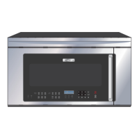
OVEN INSTALLATION
THIS OVEN CANNOT BE PROPERLYINSTALLED WITHOUT REFERRING
TOTHEMOUNTINGINSTRUCTIONSFOUNDONBOTHTEMPLATES.
THE NEXT STEP IS TO READ AND FOLLOW MOUNTING INFORMATION
ON BOTHTOPCABINETAND WALLTEMPLATES.
, _ bpace more
i i
,_ than wail
i
' thickness
i /
,,%.