TROUBLESHOOTING
CHECKING THE EFFICIENCY OF THE COMPONENTS
In order to facilitate checking of the efficiency of the component to be tested, a special CONTROL
PROCEDURE has been created. The contacts to which the tester should be applied and the correct
resistance for each component are shown in the table below.
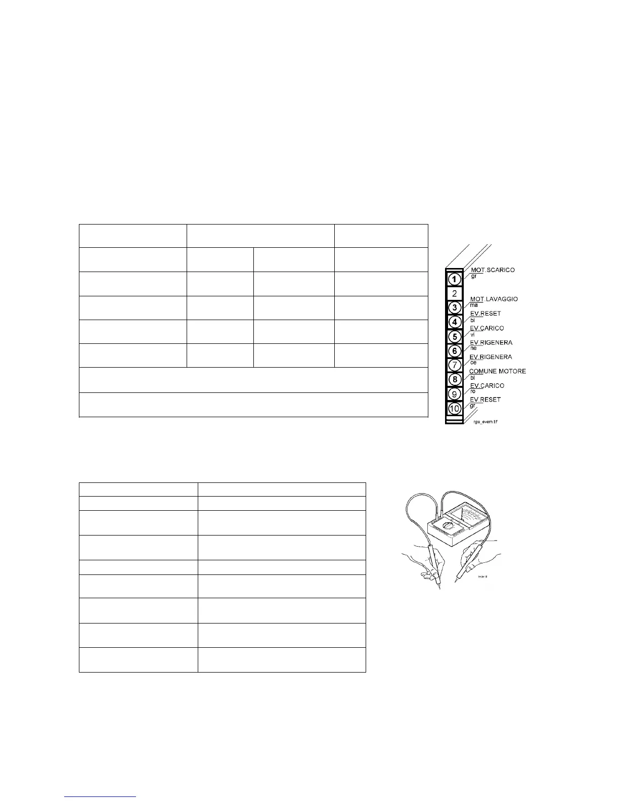
After detaching the modular wiring connector fitted to the bottom of the appliance, measure the resistance
to verify the efficiency of the components fitted to the dishwasher.
TRADITIONAL DISHWASHERS (ELECTROMECHANICAL TIMER)
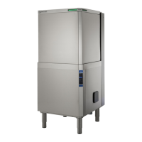
PROCEDURE: Apply the probes of the tester to the points indicated and measure the resistance.
COMPONENT TESTER PROBES
CONNECTION / COLOUR
CORRECT VALUE
MOTOR
( Drain )
1 - 8
Grey - Blue
73 Ω
ΩΩ
Ω ± 7%
MOTOR
( Washing )
3 - 8
Brown - Blue
48 Ω
ΩΩ
Ω ± 7%
REGENERATION
SOLENOID
6 - 7
Black - Light blue
5200 Ω
ΩΩ
Ω ± 8%
FILL SOLENOID AND
ANTI-FLOODING DEVICE
5 - 9
Purple -Pink
3950 Ω
ΩΩ
Ω ± 8%
RESET
SOLENOID
4 - 10
White - Grey
5200 Ω
ΩΩ
Ω ± 8%
N.B. If the resistance measured across contacts 1 - 8 and 3 - 8 is the same
(28 Ω
ΩΩ
Ω approx.), this means that the capacitor is short-circuited.
KEY: ar = orange bi = white bl = blue ce = light blue gr = grey
ma = brown ne = black ro = pink vi = purple
The remaining components can be tested in the same way or directly on the components themselves.
The correct values are listed below:
COMPONENT CORRECT VALUE
DOOR MICROSWITCH
Door closed 0 W
PRESSURE SWITCH
Empty (1-2) INFINITE
Full (1-3) 0 W
HEATING ELEMENT AND
SAFETY THERMOSTAT
2300 W 25 W ± 8%
FAN MOTOR
720 W ± 8%
INTEGRATED DETERGENT
DISPENSER
1300 W ± 8%
TEMPERATURE CONTROL
THERMOSTAT(S)
Open INFINITE
Closed 0 W
SALT SENSOR
With salt INFINITE
Without salt 0 W
RINSE-AID SENSOR
With rinse-aid INFINITE
Without rinse-aid 0 W
26