Preparing for Installation
7
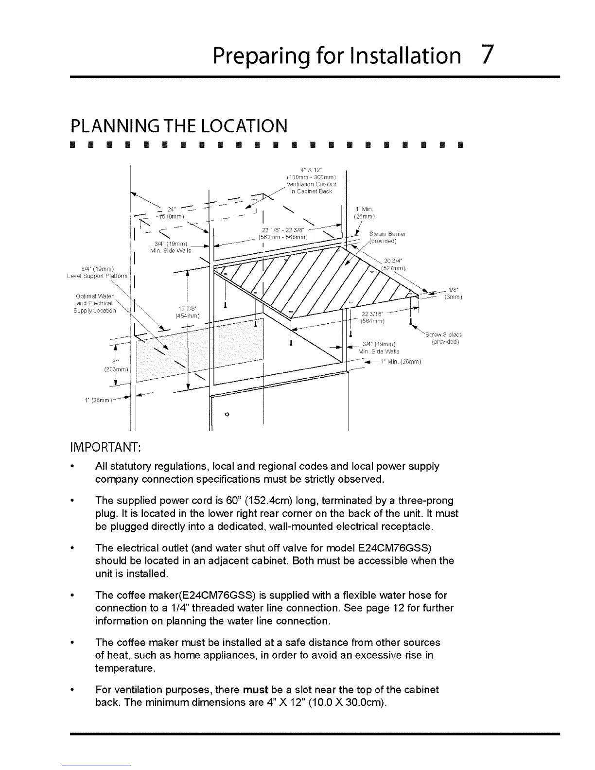
PLANNING THE LOCATION
[] !1 II [] [] [] [] [] [] ! [] [] [] [] [] [] [] [] [] [] [] []
3/4" 19mm)
Level Support Platform
\,
Opt imal Wa te r
and Electrical \\.,
Supply Location "-.,
8 ....
(203ram)
i
24" J
_lomm)
3/4" (19ram)
Min Side Walls
17 7/8"
(454mm)
4" X 12"
(100ram - 300ram)
Ventilation Cut-Out
J in Cabinet Back
22 1/8"- 22 3/8"
(582mm - 588mm)
I
Steam Barner
20 3/4"
527mm )
_ 1/8"
(3ram)
22 3/16"
(564mm) I i_ ,,_
i Screw 8 place
I 3/4" (19ram) (provided)
Min Side VYhlls
(26ram)
IMPORTANT:
• All statutory regulations, local and regional codes and local power supply
company connection specifications must be strictly observed.
The supplied power cord is 60" (152.4cm) long, terminated by a three-prong
plug. It is located in the lower right rear corner on the back of the unit. It must
be plugged directly into a dedicated, wall-mounted electrical receptacle.
The electrical outlet (and water shut off valve for model E24CM76GSS)
should be located in an adjacent cabinet. Both must be accessible when the
unit is installed.
The coffee maker(E24CM76GSS) is supplied with a flexible water hose for
connection to a 1/4" threaded water line connection. See page 12 for further
information on planning the water line connection.
The coffee maker must be installed at a safe distance from other sources
of heat, such as home appliances, in order to avoid an excessive rise in
temperature.
For ventilation purposes, there must be a slot near the top of the cabinet
back. The minimum dimensions are 4" X 12" (10.0 X 30.0cm).