15
F6.2 Installation diagrams
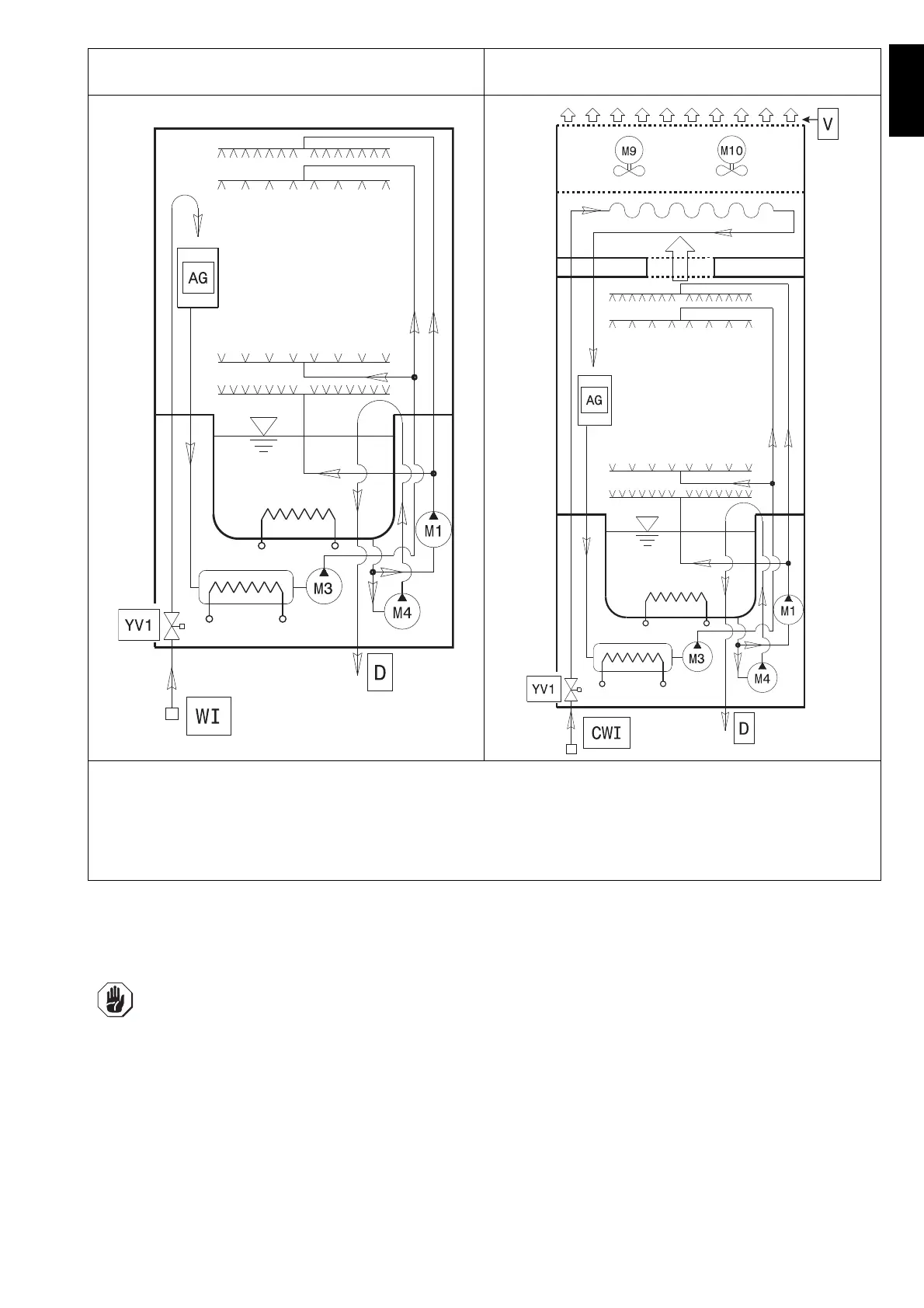
The following installation diagrams give the machine overall dimensions and position of water and electrical connec-
tions.
Plumbing circuit diagram - manual hood type with drain
pump
Plumbing circuit diagram - automatic hood type with
energy saving device (ESD)
LEGEND
WI = Water inlet
CWI = Cold water inlet (~ 15°C)
M1 = Wash pump
M3 = Rinse pump
M4 = Drain pump
M9 = ESD fan motor
M10 = ESD fan motor
AG = Air Gap
YV1 = Filling solenoid valve
V = Ventilation
IMPORTANT!
For models without energy saving device (ESD), make sure to install an extractor hood to remove
the steam produced by the machine.
For models with energy saving device (ESD), it is not necessary to install an extractor hood
unless the current regulations in the country of use require it.
The hood air flow must be calculated taking into account the type of installation and the work
environment where it is installed. In any case, an air flow rate of between 1000 m
3
/h and 1500 m
3
/
h is recommended.
 Loading...