18
PLMV169DCC
5. Reconnect all leads removed from components during testing.
6. Reinstall the outer case (cabinet).
7. Reconnect the power supply cord after the outer case is installed.
8. Run the oven and check all functions.
TEST PROCEDURES
PROCEDURE
LETTER
COMPONENT TEST
I HOOD THERMAL CUT-OUT TEST
1. Disconnect the power supply cord, and then remove outer case.
2. Open the door and block it open.
3. Discharge high voltage capacitor.
4. A continuity check across the thermal cut-out terminals should indicate an open circuit unless the
temperature of the thermal cut-out reaches approximately 140
O
F(60
O
C) or more. At that temperature,
the contacts will close. The thermal cut-out opens automatically at approximately 113
O
F(45
O
C).
5. Reconnect all leads removed from components during testing.
6. Reinstall the outer case (cabinet).
7. Reconnect the power supply cord after the outer case is installed.
8. Run the oven and check all functions.
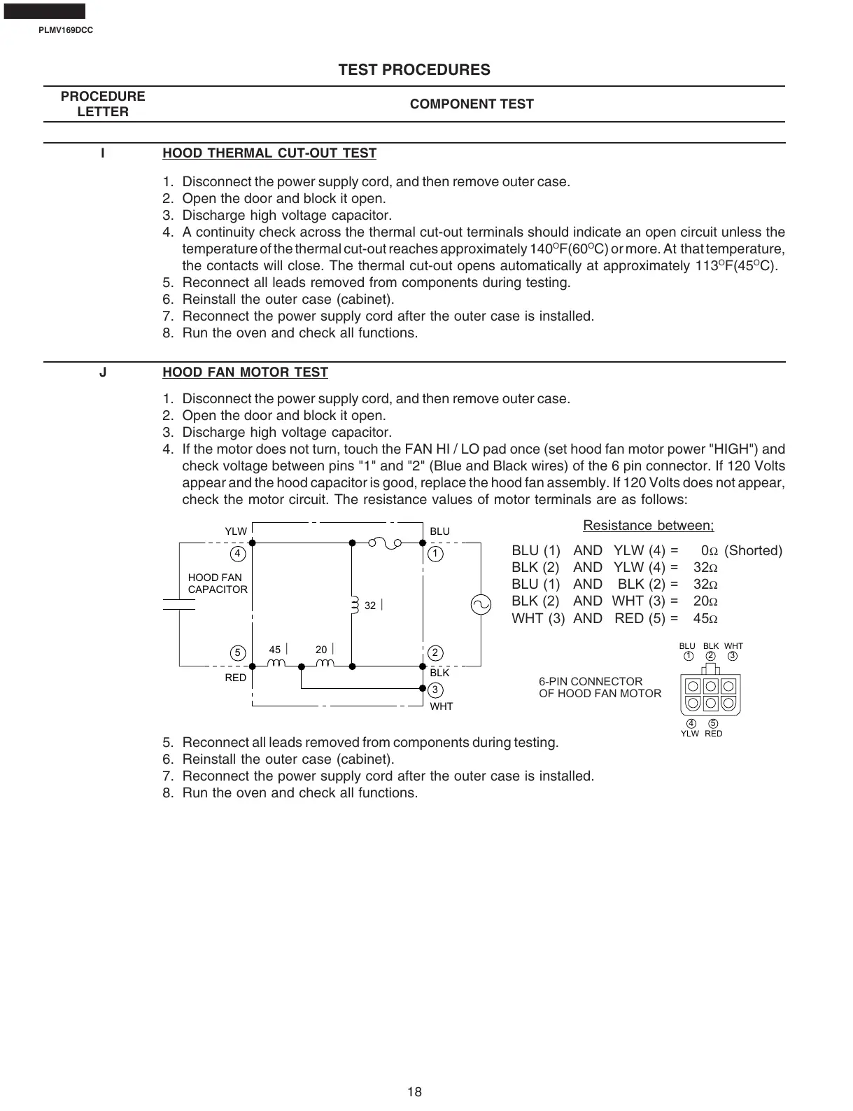
J HOOD FAN MOTOR TEST
1. Disconnect the power supply cord, and then remove outer case.
2. Open the door and block it open.
3. Discharge high voltage capacitor.
4. If the motor does not turn, touch the FAN HI / LO pad once (set hood fan motor power "HIGH") and
check voltage between pins "1" and "2" (Blue and Black wires) of the 6 pin connector. If 120 Volts
appear and the hood capacitor is good, replace the hood fan assembly. If 120 Volts does not appear,
check the motor circuit. The resistance values of motor terminals are as follows:
Resistance between;
BLU (1) AND YLW (4) = 0
Ω
(Shorted)
BLK (2) AND YLW (4) = 32
Ω
BLU (1) AND BLK (2) = 32
Ω
BLK (2) AND WHT (3) = 20
Ω
WHT (3) AND RED (5) = 45
Ω
123
45
BLU BLK WHT
YLW RED
6-PIN CONNECTOR
OF HOOD FAN MOTOR
32
20 45
HOOD FAN
CAPACITOR
YLW
RED
BLU
BLK
1
2
3
WHT
4
5