Do you have a question about the Electrolux PLMV169DCE and is the answer not in the manual?
Safety checks and procedures before operating or servicing the microwave oven to prevent hazards.
Steps to take before starting any repair work on the microwave oven.
Procedures after completing tests and before final reassembly.
Final steps after completing repair work and reassembly.
Defines limits for microwave leakage and interlock switch requirements.
Steps to prepare the oven and test equipment for leakage measurement.
Procedure for conducting the closed-door microwave leakage test.
Detailed technical specifications of the microwave oven, including dimensions and power requirements.
Essential safety guidelines for properly grounding the microwave oven.
Explanation of the oven's operational flow and component functions.
Details on how variable power levels are controlled and timed.
Description of vertical, horizontal, and recirculation ventilation configurations.
Explanation of how the sensor cooking function works and its sequence.
Guidance on diagnosing and resolving common operational problems with the oven.
Procedure to test the magnetron for proper assembly and functionality.
Method to measure microwave power output using a water temperature rise test.
Steps to test the high voltage rectifier for proper operation using an ohmmeter.
Procedure to test the high voltage capacitor for shorts or opens.
Testing the primary interlock switch for correct operation based on door position.
Testing the door sensing switch for proper activation with door open/closed.
Procedure to test the monitor switch's continuity based on door and latch operation.
Test to verify the hood thermal cut-out's function at temperature thresholds.
Procedure to test the hood fan motor's operation and check resistance values.
Steps for testing the touch control panel and key unit for defects.
Procedure to test the Absolute Humidity sensor's functionality in cooking.
Steps to diagnose control unit defects by simulating sensor input.
Testing the noise filter unit for open or short circuits using an ohmmeter.
Overview of the touch control panel's units and signals.
Explanation of the Key Unit's function and interaction with the LSI.
Description of the Control Unit's components and circuits.
Details of the Large Scale Integration (LSI) chip's functions and signals.
Description of the sensor's physical components and thermistors.
Explanation of the sensor's bridge circuit and amplifier operation.
How the detector circuit interfaces with the LSI for sensor cooking.
Guidelines for safely handling electronic components like CMOS LSI.
Procedures for servicing the touch control panel with external power.
List of tools required for touch control panel servicing.
Additional precautions when working with the control unit and its components.
Critical warnings about high voltage hazards during servicing.
Precautions to prevent electric shock and ensure correct wiring.
Step-by-step instructions for removing the hood exhaust louver.
Procedure for safely removing the oven unit from its wall installation.
Instructions for removing the outer casing of the microwave oven.
Steps to remove and reinstall the power transformer.
Procedures for removing hood fan motor, duct, oven lamp socket, and AH sensor.
Detailed steps for removing the magnetron assembly.
Instructions for removing the high voltage rectifier and capacitor components.
Procedure for removing the hood fan thermal cut-out.
Steps to remove the cavity thermal cut-out.
Procedure for removing the cooling fan motor and its components.
Instructions for removing the turntable motor assembly.
Steps to remove the stirrer motor.
Procedure for removing the oven lamp and its socket.
Procedure for removing the positive lock connector.
Removing door sensing, secondary interlock, and monitor switches.
Steps to remove the oven door assembly.
Instructions for re-installing the oven door assembly.
Adjusting door switches for proper alignment and operation.
Procedure for removing the choke cover from the door.
Steps to remove the door frame assembly.
Instructions for removing the door glass from the frame.
List of electrical components with part numbers and quantities.
List of cabinet and structural components with part numbers.
List of parts related to the control panel assembly.
List of various oven internal and external parts.
List of all components related to the oven door assembly.
List of miscellaneous items including screws, manuals, and templates.
Listing of fasteners, washers, and miscellaneous hardware.
| Capacity | 1.6 cu. ft. |
|---|---|
| Power Output | 1000 Watts |
| Control Type | Electronic Touch |
| Turntable | Yes |
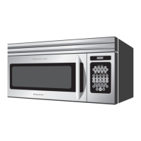
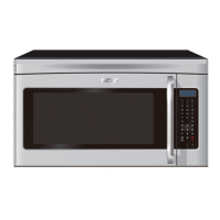
| Installation Type | Over-the-Range |
| Color | Stainless Steel |
| Type | Microwave Oven |
| Turntable Diameter | 13.5 inches |