20
PLMV169DCC
TEST PROCEDURES
PROCEDURE
LETTER
COMPONENT TEST
6) Re-install the outer case (cabinet).
7) Reconnect the power supply cord after the outer case is installed.
8) Run the oven and check all functions.
2. Control Unit.
The following symptoms indicate a defective control unit. Before replacing the control unit, perform
the Key unit test (Procedure M) to determine if control unit is faulty.
2-1 In connection with pads.
a) When touching the pads, a certain group of pads do not produce a signal.
b) When touching the pads, no pads produce a signal.
2-2 In connection with indicators
a) At a certain digit, all or some segments do not light up.
b) At a certain digit, brightness is low.
c) Only one indicator does not light.
d) The corresponding segments of all digits do not light up; or they continue to light up.
e) Wrong figure appears.
f) A certain group of indicators do not light up.
g) The figure of all digits flicker.
2-3 Other possible problems caused by defective control unit.
a) Buzzer does not sound or continues to sound.
b) Clock does not operate properly.
c) Cooking is not possible.
When testing is completed,
1) Disconnect the power supply cord, and then remove outer case.
2) Open the door and block it open.
3) Discharge high voltage capacitor.
4) Reconnect all leads removed from components during testing.
5) Re-install the outer case (cabinet).
6) Reconnect the power supply cord after the outer case is installed.
7) Run the oven and check all functions.
1. Disconnect the power supply cord, and then remove outer case.
2. Open the door and block it open.
3. Discharge high voltage capacitor.
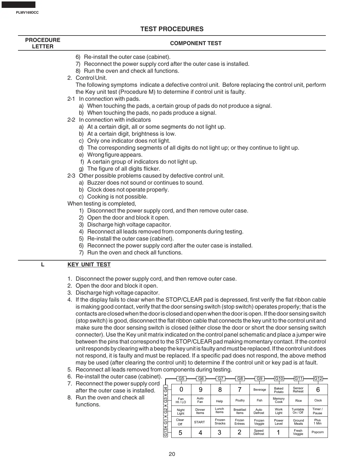
4. If the display fails to clear when the STOP/CLEAR pad is depressed, first verify the flat ribbon cable
is making good contact, verify that the door sensing switch (stop switch) operates properly; that is the
contacts are closed when the door is closed and open when the door is open. If the door sensing switch
(stop switch) is good, disconnect the flat ribbon cable that connects the key unit to the control unit and
make sure the door sensing switch is closed (either close the door or short the door sensing switch
connecter). Use the Key unit matrix indicated on the control panel schematic and place a jumper wire
between the pins that correspond to the STOP/CLEAR pad making momentary contact. If the control
unit responds by clearing with a beep the key unit is faulty and must be replaced. If the control unit does
not respond, it is faulty and must be replaced. If a specific pad does not respond, the above method
may be used (after clearing the control unit) to determine if the control unit or key pad is at fault.
5. Reconnect all leads removed from components during testing.
6. Re-install the outer case (cabinet).
7. Reconnect the power supply cord
after the outer case is installed.
8. Run the oven and check all
functions.
L KEY UNIT TEST
G5
5
0
4
9
3
8
2
7
1
6
G6
Auto
Defrost
Night
Light
Clear
Off
Fresh
Veggie
Work
Light
Power
Level
Plus
1 Min
Popcorn
Fan
HI / LO
Turntable
On / Off
Help
Dinner
Items
Lunch
Items
Clock
G7 G8 G9 G10 G11 G12
G13 G1 G2 G3 G4
Timer /
Pause
START
Auto
Fan
Frozen
Snacks
Frozen
Entrees
Breakfast
Items
Poultry
Beverage
Fish
Frozen
Veggie
Speed
Defrost
Baked
Potato
Memory
Cook
Sensor
Reheat
Rice
Ground
Meats