37
PLMV169DCC
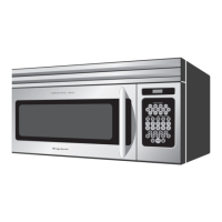
CONTROL PANEL ASSEMBLY, CONTROL UNIT AND KEY UNIT REMOVAL
1. Disconnect the power supply cord.
2. Open the door and block it open.
3. Remove one (1) screw holding the hood exhaust louver to
oven cavity front flange.
4. Remove the hood exhaust louver from the oven by
pushing the right and left tabs of the hood exhaust louver.
(Refer to procedure of "HOOD EXHAUST LOUVER
REMOVAL")
5. Remove one (1) screw holding the control panel to the
oven cavity front face plate.
6. Release the control panel from the oven cavity front face
plate by lifting it up.
7. Disconnect the wire leads from the relays RY1 and RY2.
8. Disconnect the connectors CN-A, CN-B and CN-E from
the control unit.
9. Remove the control panel assembly from the oven.
10.Now, the control panel assembly is free.
11.Disconnect the connector CN-G from the control unit.
12.Release the two (2) tabs of LCD holder from the two (2)
holes of the key fixing plate.
13.Release the four (4) tabs holding the LCD holder to the
tcontrol panel.
14.Remove two (2) screws holding the power unit to the key
fixing plate.
15.Release the two (2) tabs holding the power unit to the key
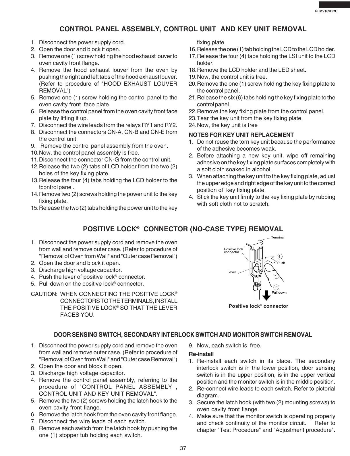
POSITIVE LOCK
®
CONNECTOR (NO-CASE TYPE) REMOVAL
1. Disconnect the power supply cord and remove the oven
from wall and remove outer case. (Refer to procedure of
"Removal of Oven from Wall" and "Outer case Removal")
2. Open the door and block it open.
3. Discharge high voltage capacitor.
4. Push the lever of positive lock
®
connector.
5. Pull down on the positive lock
®
connector.
CAUTION: WHEN CONNECTING THE POSITIVE LOCK
®
CONNECTORS TO THE TERMINALS, INSTALL
THE POSITIVE LOCK
®
SO THAT THE LEVER
FACES YOU.
Terminal
Push
Pull down
4
5
Lever
Positive lock¨
connector
Positive lock
®
connector
DOOR SENSING SWITCH, SECONDARY INTERLOCK SWITCH AND MONITOR SWITCH REMOVAL
1. Disconnect the power supply cord and remove the oven
from wall and remove outer case. (Refer to procedure of
"Removal of Oven from Wall" and "Outer case Removal")
2. Open the door and block it open.
3. Discharge high voltage capacitor.
4. Remove the control panel assembly, referring to the
procedure of "CONTROL PANEL ASSEMBLY ,
CONTROL UNIT AND KEY UNIT REMOVAL".
5. Remove the two (2) screws holding the latch hook to the
oven cavity front flange.
6. Remove the latch hook from the oven cavity front flange.
7. Disconnect the wire leads of each switch.
8. Remove each switch from the latch hook by pushing the
one (1) stopper tub holding each switch.
9. Now, each switch is free.
Re-install
1. Re-install each switch in its place. The secondary
interlock switch is in the lower position, door sensing
switch is in the upper position, is in the upper vertical
position and the monitor switch is in the middle position.
2. Re-connect wire leads to each switch. Refer to pictorial
diagram.
3. Secure the latch hook (with two (2) mounting screws) to
oven cavity front flange.
4. Make sure that the monitor switch is operating properly
and check continuity of the monitor circuit. Refer to
chapter "Test Procedure" and "Adjustment procedure".
fixing plate.
16.Release the one (1) tab holding the LCD to the LCD holder.
17.Release the four (4) tabs holding the LSI unit to the LCD
holder.
18.Remove the LCD holder and the LED sheet.
19.Now, the control unit is free.
20.Remove the one (1) screw holding the key fixing plate to
the control panel.
21.Release the six (6) tabs holding the key fixing plate to the
control panel.
22.Remove the key fixing plate from the control panel.
23.Tear the key unit from the key fixing plate.
24.Now, the key unit is free
NOTES FOR KEY UNIT REPLACEMENT
1. Do not reuse the torn key unit because the performance
of the adhesive becomes weak.
2. Before attaching a new key unit, wipe off remaining
adhesive on the key fixing plate surfaces completely with
a soft cloth soaked in alcohol.
3. When attaching the key unit to the key fixing plate, adjust
the upper edge and right edge of the key unit to the correct
position of key fixing plate.
4. Stick the key unit firmly to the key fixing plate by rubbing
with soft cloth not to scratch.