28
GLMV169DBD
GLMV169DQD
GLMV169DSD
PLMV169DCE
ON
OFF
H : GND
L
ON
OFF
H : GND
L
ON
OFF
H : GND
L
L
1
H
L
AC
CURRENT
WORK
LIGHT
NIGHT
LIGHT
H
2
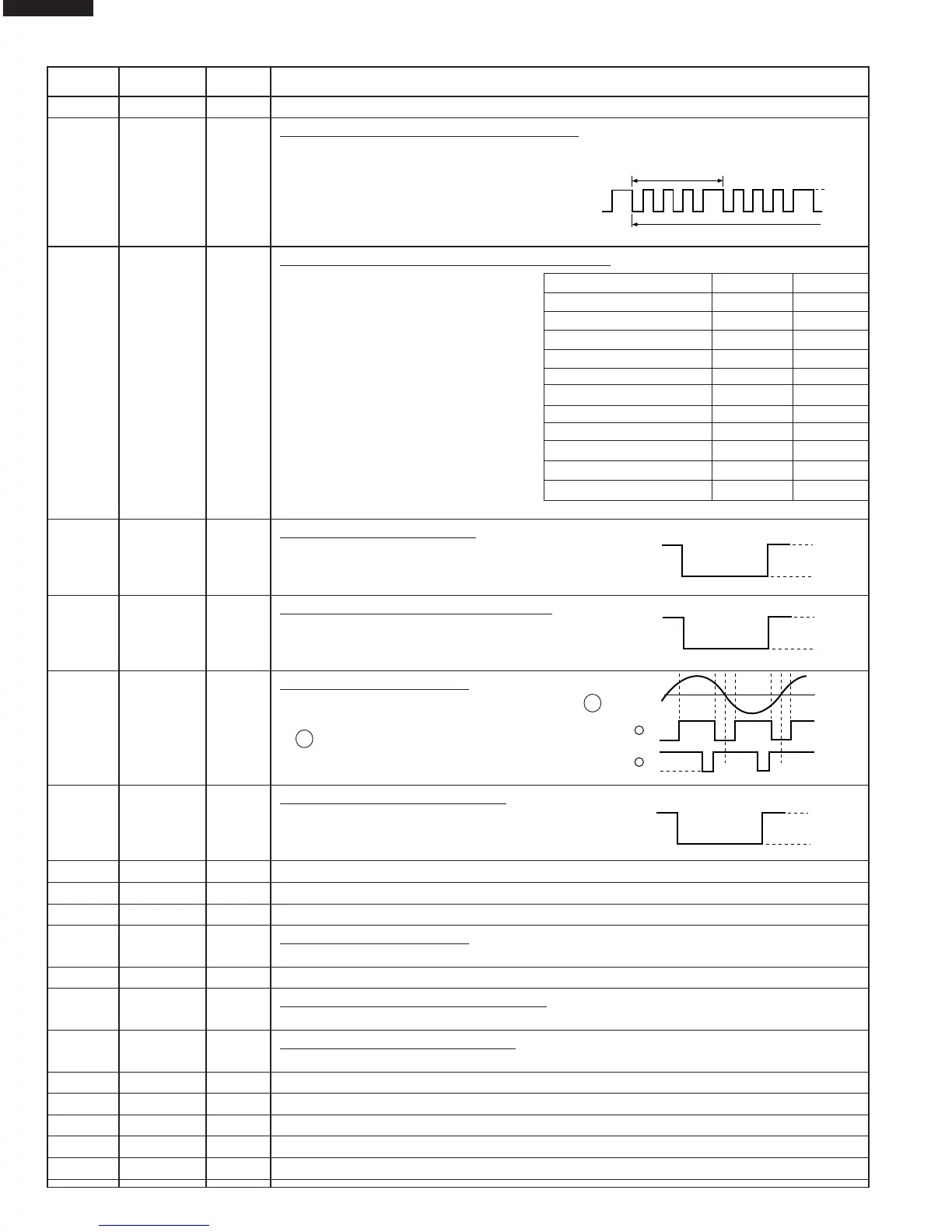
20-22 P21-P23 OUT Terminal not used.
23 P24 OUT
Oven lamp and Fan motor driving signal.
To turn on and off the shut off relay(RY1). The square waveform voltage is delivered to
the RY1 driving circuit and RY2 control circuit.
24 P25 OUT Magnetron high-voltage circuit driving signal.
To turn on and off the cook
relay(RY2). In P-HI operation, the
signals holds "L" level during mi-
crowave cooking and "H" level
while not cooking. In other cook-
ing modes (P-90,P-80,P-70,P-
60,P-50,P-40,P-30,P-20,P-10,P-
0) the signal turns to "H" level and
"L" level in repetition according to
the power level.
25 P26 OUT Hood motor driving signal.
To turn on and off relay(RY4). "L" level: During
Hood motor ON. "H" level: During Hood motor
OFF.
26 P27 OUT
Hood motor high / low driving signal.
To turn on and off relay(RY5). "L" level: During
Hood motor high. "H" level: During Hood motor
low.
27 P30 OUT
Hood lamp driving signal.
To turn on and off solid state relay(SSR1). " 1 "
level: During Hood lamp ON (WORK LIGHT level).
" 2 " level: During Hood lamp ON (NIGHT
LIGHT level). "H" level: During Hood lamp OFF.
28 P31 OUT Turntable motor driving signal.
To turn on and off relay(RY3). "L" level: During
Turntable ON. "H" level: During Turntable OFF or
during the oven is off condition.
29 P32-P37 OUT Terminal not used.
30-34 P33-P37 OUT Used for initial balancing of the bridge circuit (absolute humidity sensor)
35 CVCC IN Connected to GND.
36 VSS IN
Power source voltage:-5V.
The power source voltage to the LSI is input to VSS terminal. Connected to VC.
37-38 V3-V2 IN Terminal not used.
39-40 V1-V0 IN
Power source voltage input terminal.
Standard voltage for LCD. Connected to GND.
41 VCC IN
Power source voltage: GND (0V).
The power source voltage to drive the LSI is input to VCC terminal.
42-45
COM4-COM1
OUT Terminal not used.
46-65
SEG1-SEG20
OUT Terminal not used.
66-79 P74-P91 OUT Data output terminal to LCD driver IC3.
80-85
SEG35-SEG40
OUT Terminal not used.
86 P40 OUT Terminal not used.
Pin No. Signal I/O Description
VARI-MODE ON TIME OFF TIME
P-HI (100% power) 32 sec. 0 sec.
P-90 (approx. 90% power) 30 sec. 2 sec.
P-80 (approx. 80% power) 26 sec. 6 sec.
P-70 (approx. 70% power) 24 sec. 8 sec.
P-60 (approx. 60% power) 22 sec. 10 sec.
P-50 (approx. 50% power) 18 sec. 14 sec.
P-40 (approx. 40% power) 16 sec. 16 sec.
P-30 (approx. 30% power) 12 sec. 20 sec.
P-20 (approx. 20% power) 8 sec. 24 sec.
P-10 (approx. 10% power) 6 sec. 26 sec.
P-0 (0% power) 0 sec. 32 sec.
During cooking
L : -5V
H : GND
16.7 msec.