29
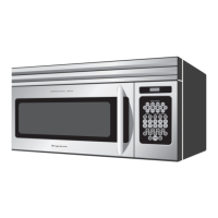
GLMV169DBD
GLMV169DQD
GLMV169DSD
PLMV169DCE
Pin No. Signal I/O Description
87 P41 IN Signal similar to AN10.
When either G13 line on key matrix is touched, acorresponding signal will be input into
P41.
88 P42 IN
Signal similar to AN10.
When either G12 line on key matrix is touched, acorresponding signal will be input into
P42.
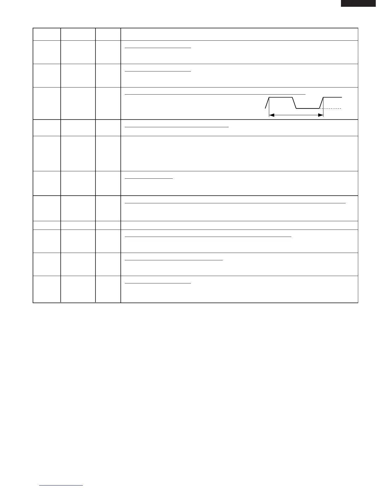
89 IRQ0 IN
Signal synchronized with commercial power source frequency.
This is the basic timing for time processing of LSI.
90 AVCC IN A/D converter power source voltage.
The power source voltage to drive the A/D converter in the LSI. Connected to GND.
91 AN0 IN Used for initial balancing of the bridge circuit (absolute humidity sensor). This input is an
analog input terminal from the AH sensor circuit, and connected to the A/D converter built
into the LSI.
92 AN0-AN1 IN AH sensor input.
This input is an analog input terminal from the AH sensor circuit, and connected to the
A/D converter built into the LSI.
93 AN2 IN
To input signal which communicates the door open/close information to LSI.
Door closed; "H" level signal(0V).
Door opened; "L" level signal(-5V).
94 AN3 IN Terminal not used.
95-98 AN4-AN7 IN
Terminal to change cooking input according to the Model.
By using the A/D converter contained in the LSI, DC voltage in accordance with the Model
in operation is applied to set up its cooking constant.
99 AN8 IN
Input terminal to judge the model.
The signal out of P16 will be input into AN8 through G2 line on key matrix. The LSI will
judge the model by this signal.
100 AN9 IN
Signal similar to AN10.
When either G11 line on key matrix is touched, a corresponding signal will be input into
AN9.
16.7 msec.
H : GND
L : -5V