22
© 2006, Elektro-Automatik GmbH & Co. KG
Irrtümer und Änderungen vorbehalten
EN
© 2009, Elektro-Automatik GmbH & Co. KG
Handling the device
Reset conguration
If YES is chosen at the conrmation prompt „Are
you sure?“ all editable parameters are reset to their
default values. With NO chosen, all settings remain
unaltered.
After a conguration reset, the value „U output“ of
the selected voltage proles has to be submitted
once again.
Lock setup
After entering a 4 digit PIN code with the arrow but-
tons, the control panel is locked, except the unlock
button. The four numbers can be 0 - 15, which results
in 16
4
= 65536 combinations. Unlocking is done the
same way, by entering the PIN code again. If the PIN
code is lost, the device can only be accessed again
by doing a „Reset conguration“. See above.
Remind, that a conguration reset will reset all settings
to their default values!
Digital remote control
With the optionally available, digital interface cards
(USB, RS232 or CAN) the device can be completely
remotely controlled and monitored. For details of
features and technical specs see the user manual of
the interface cards.
With CAN, multiple power supplies can be networ-
ked.
Analogue remote control
Set values that control output voltage and current
can be given to set value inputs VSEL and CSEL
with control voltages of 0...10V or 0...5V, depending
on the selected control voltage range (see section
„The setup menu“).
The actual output values of voltage and current are
put out as monitoring voltages to outputs VMON and
CMON with 0...10V or 0....5V, depending on the se-
lected control voltage range (see section „The setup
menu“).
Before controlling the device remotely is has to be
switched to remote control by pin 7 „Remote“. Both
values must be given. If only one of both is going to
be adjusted, the other one can be tied to VREF in
order to be 100%.
Remote control by analogue interface is indicated in
the display with the status text „extern“.
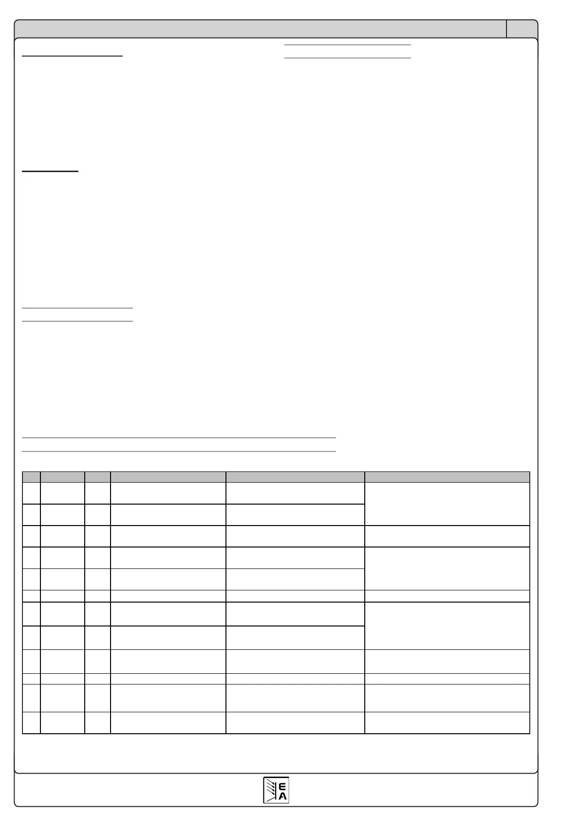
Pin assignment and technical specs of the analogue interface
Typ
1
Description Level Electrical specifications
1
VSEL
AI Set value: voltage
0….10V correspond to
0….100% U
Nom
Accuracy 0.2%, U
Max
= 12V
CSEL
AI Set value: current
0….10V correspond to
0….100% I
Nom
3
VREF
AO Reference voltage 10V / 5V
Accuracy < 0.1% bei I
Max
= 10mA
Short-circuit-proof against AGND
4
VMON
AO Actual value: voltage
0….10V correspond to
0….100% von U
Nom
5
CMON
AO Actual value: current
0….10V correspond to
0….100% von I
Nom
6
AGND
Reference for analogue signals For VSEL, CSEL, CMON, VMON, VREF
7
Remote
DI
Activate external controls
External = Low (U
Low
<1V),
Internal = High (U
High
>4V)
Off = Low (U
Low
<1V)
On = High (U
High
>4V)
Various errors like
OVP, OT
Low = No error (U
Low
<1V)
High = Error (U
High
>4V)
U
Max
= 15V, I
Max
= -10mA
Quasi open collector with pull-up to Vcc
2
10
DGND
Reference for digital signals For control and condition signals
11
CV
DO
Low = Voltage controlled (U
Low
<1V)
High = Current controlled (U
High
>4V)
U
Max
= 15V, I
Max
= -10mA
Quasi open collector with pull-up to Vcc
2
12
+VCC
AO Auxiliary voltage 12….16V
I
Max =
24mA
Short-circuit-proof against DGND
1)
AI = Analogue input, AO = Analogue output, DI = digital input, DO = digital output
U
Max
= 0…15V
I
Max
= -3mA bei 15V
Accuracy < 0.2% bei I
Max
= +2mA
Short-circuit-proof against AGND
 Loading...