Page 25
EA Elektro-Automatik GmbH
Helmholtzstr. 31-37 • 41747 Viersen
Germany
Fon: +49 2162 / 3785-0
Fax: +49 2162 / 16230
www.elektroautomatik.de
ea1974@elektroautomatik.de
PSB 9000 3U Series
1.9 Construction and function
1.9.1 General description
The power supplies of the PSB 9000 3U series are so-called bidirectional devices, incorporating the function of a
laboratory power supply (source) and an electronic load (sink) into one unit. They allow for easy setup of applica-
tions according to the source-sink principle with a minimum of required hardware and cabling.
The sink feature is furthermore included with an energy recovery function which inverts the consumed DC energy
with an eciency of up to 95% and feeds it back into the local mains.
Apart from basic functions of power supplies, set point curves can be generated by the integrated function gen-
erator (sine, rectangular, triangular and other curve types). Arbitrary generator curves (99 points) can be saved to
and loaded from an USB stick. Some of the functions even oer to dynamically switch between source and sink
operation mode by setting up positive (for the source) or negative (for the sink) current set values.
For remote control the devices are provided as standard with an USB slot on the back side as well as a galvani-
cally isolated analog interface.
Via optional plug-in interface modules, other digital interfaces such as for Ethernet, RS232, Probus, ProNet,
ModBus TCP, CAN, CANopen or EtherCAT can be added. These enable the devices to be connected to standard
industrial buses simply by changing or adding a small module. The conguration, if necessary at all, is simple.
In addition, the devices oer as standard the possibility for parallel connection in so-called Share bus operation
for constant current sharing, plus a true master-slave connection with totalling of all actual values is also provided
as standard. Operating in this way allows for up to 16 units to be combined to a single system with a total power
of up to 240 kW.
All models are controlled by microprocessors for fast and exact measurement and display of actual values.
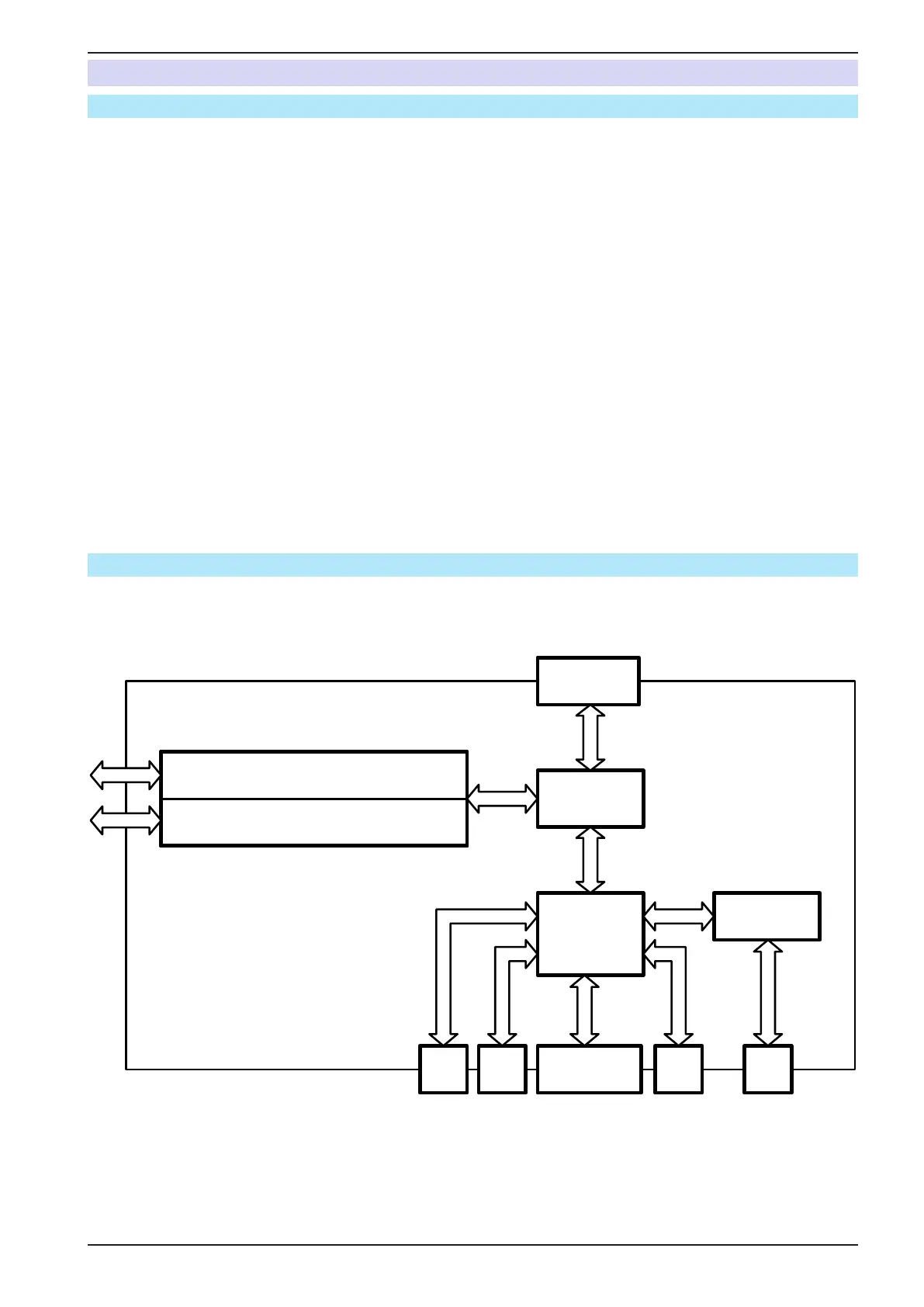
1.9.2 Block diagram
The block diagram illustrates the main components inside the device and their relationships.
There are digital, microprocessor controlled components (KE, DR, HMI), which can be target of rmware updates.
Controller
(DR)
Commu-
nication
(KE)
HMI
MS
Anybus /
GPIB (opt.)
USBUSB
Ana
log
Share &
Sense
PSB 9000
Block diagram
=
≈
=
≈
Power block
1...3
AC
DC
 Loading...