Page 40
EA Elektro-Automatik GmbH
Helmholtzstr. 31-37 • 41747 Viersen
Germany
Fon: +49 2162 / 3785-0
Fax: +49 2162 / 16230
www.elektroautomatik.de
ea1974@elektroautomatik.de
PSB 9000 3U Series
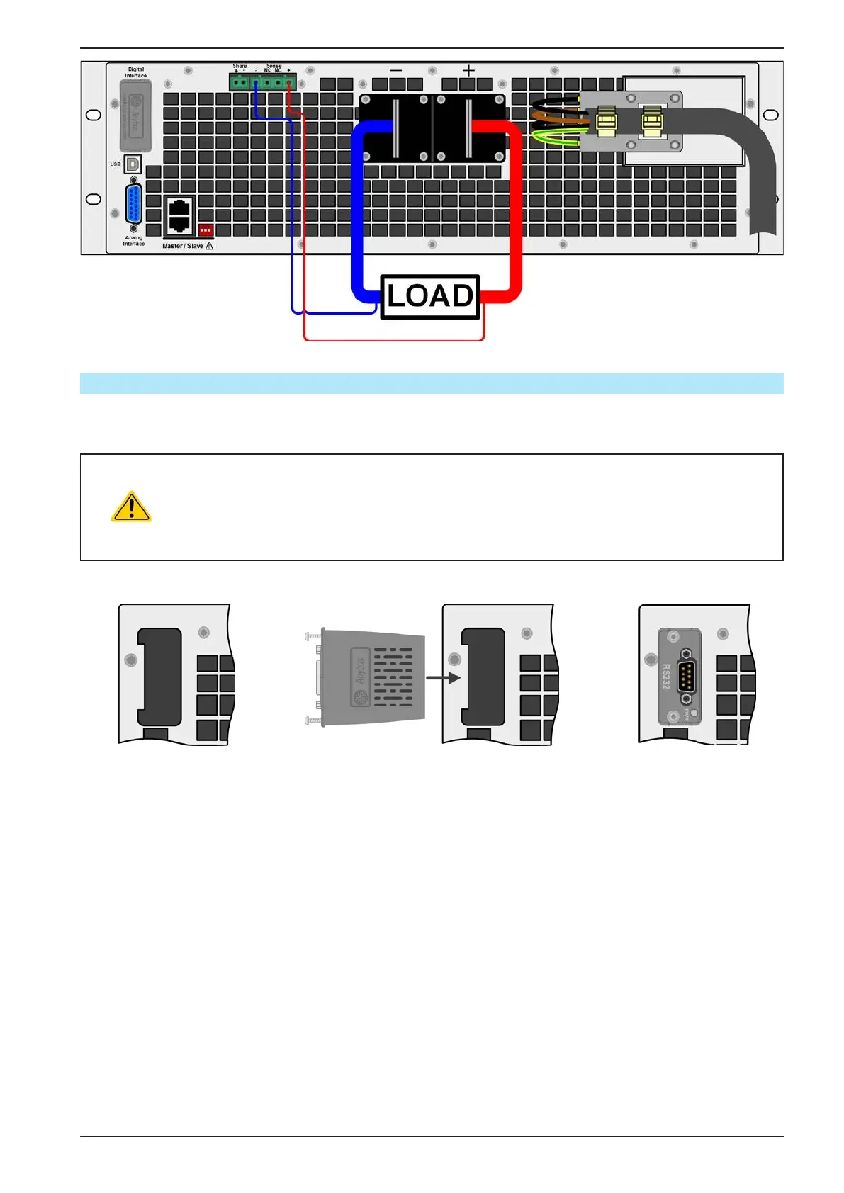
Figure 10 - Example for remote sensing wiring with load in source mode (sink mode will be wired identically)
2.3.9 Installation of an interface module
The optionally obtainable interface modules can be retrotted by the user and are exchangeable with each other.
The settings for the currently installed module vary and need to be checked and, if necessary, corrected on initial
installation and after module exchange.
• Common ESD protection procedures apply when inserting or exchanging a module.
• The device must be switched o before insertion or removal of a module
• Never insert any other hardware other than an interface module into the slot
• If no module is in use it is recommended that the slot cover is mounted in order to avoid internal
dirtying of the device and changes in the air ow.
Installation steps:
1. 2. 3.
Remove the slot cover.
If needed use a screw
driver.
Check that the fixing
screws of an already
installed module are fully
retracted. If not, unscrew
them (Torx 8) and re-
move module.
Insert the interface module into the slot. The
shape ensures correct alignment.
When inserting take care that it is held as
close as possible to a 90° angle to the rear
wall of the device. Use the green PCB which
you can recognize on the open slot as guide.
At the end is a socket for the module.
On the bottom side of the module are two
plastic nibs which must click into the green
board (PCB) so that the module is properly
aligned on the rear wall of the device.
The screws (Torx 8) are pro-
vided for xing the module
and should be fully screwed
in. After installation, the
module is ready for use and
can be connected.
Removal follows the reverse
procedure. The screws can
be used to assist in pulling
out the module.
 Loading...