TEST GSM SET TIME
ENTER PIN
SET TIME
CONSTANTS
13
ENTER PIN
SET HOUR
2
INSTALLATION
Install the thermostat at a suitable place where its operation will not be affected by direct fl ow of hot air from a heating source, by sunshine or
other disturbing effects. Do not install it on an external wall either. The installation height should be at least 1.5 m above the ground. Locate the
thermostat in the so-called reference room, such as the living room (the heat source will be switched according to the temperature in this room).
The installation and battery replacement can only be done by a person with adequate qualifi cation!
Before installation, disconnect the power supply!
1) Switch off the main circuit breaker.
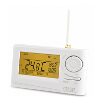
2) Remove the control part from the bottom cover of the device (Fig. 1).
3) Chip off the plastic piece in the middle of the bottom cover to lead in the conductors.
4) Run the conductors through the hole and connect them to the terminal board, see the wiring diagram.
5) Fasten the bottom cover to the wiring box by means of screws (Fig. 2).
6) Insert the activated SIM card into the SIM card holder at the back of the control part.
7) If you want to back up the time, install the fully charged rechargeable batteries (see Fig. 3).
8) Mount the control part onto the bottom cover (Fig. 2).
9) Connect the power supply to the connector No. 1 or No. 2 (see page 1).
ATTENTION PT32 GST MUST BE POWERED FROM ONE SOURCE!!
10) Switch on the main circuit breaker and test the thermostat for correct connection, see page 3 (TEST).
11) Upon the fi rst start (or reset), the thermostat shows the “SET CLOCK”, “ENTER PIN” messages; set the current time and date
acc. to the instructions on page 3, enter the PIN acc. to page 7 and select language acc page 5.
Fig.1
Fig.2
MENU
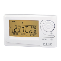
FIRST SWITCH-ON
Wiring diagram:
PT32GST
BOILER
*
*
potential-free
(voltage-free) contact
The thermostat terminals are
marked differently with every
boiler type; therefore, observe the
wiring recommended by the boiler
manufacturer!
connector for the
AD05 power source
connection
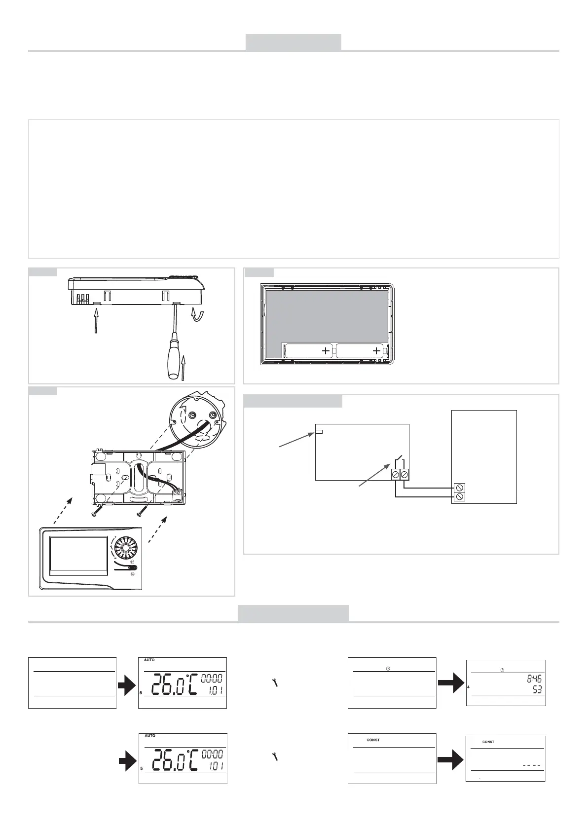
Fig.3
AA rechargeable
battery
AA rechargeable
battery
The thermostat enables backup of time in
case of power failure. You must use rechar-
geable batteries 2x1,2 V, type AA/R6. After
power failure, the time remains current (ap-
proximate service life: 2 years, according to
the type of batteries used).
The advantage is recharging of the batteries
after the power supply is restored.
CAUTION: THE BATTERIES ARE NOT USED
FOR SUPPLYING THE THERMOSTAT, FOR
WHICH THE AD05-jack POWER SOURCE
MUST BE USED (see page 1).
GSM module is being
checked.
Press the “ MENU “, button twice;
choose the CLOCK mode by
turning the “ „ button and make
the settings acc. to page 3.
Press the “ MENU “, button twice;
choose the CONST mode by
turning the “
„ button; move on
to set CONST13 acc. to page 7.
After you switch on PT32GST fi rst, the following message appears on the LCD; follow the instructions to make the corresponding settings
(INSERT SIM CARD BEFORE POWER CONNECTION):
COM NO
ATTENTION!
NEVER TAKE OUT THE SIM CARD FROM HOLDER IF THE THERMOSTAT
CONNECTED TO POWER SUPPLY!