5-3. How to Make Measurements
WARNING
1. To avoid electrical shock hazard and/or damage to
the meter, do not measure voltages that might
exceed 500V above earth ground.
2. Before using the instrument, inspect the test leads,
connectors, and probes for cracks, breaks, or grazes
in the insulation.
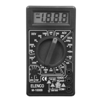
DC Voltage Measurement
1. Plug the red test lead into the “V W mA” jack and the
black test lead into the “COM” jack.
2. Set the RANGE switch to the desired DCV position.
If the voltage to be measured is not known
beforehand, set the switch to the highest range and
reduce it until a satisfactory reading is obtained.
3. Connect the test leads to the device or circuit being
measured.
4. Turn on the power of the device or circuit being
measured. The voltage value will appear on the
digital display along with the voltage polarity.
Resistance
200W 0.1W +(0.8% of rdg+2dgt)
2kW 1W +
(1% of rdg+2dgt)
20kW 10W +
(1% of rdg+2dgt)
200kW 100W +
(1% of rdg+2dgt)
2000kW 1kW +
(1% of rdg+2dgt)
OVERLOAD PROTECTION: 15 seconds maximum 220Vrms on
all ranges.
MAXIMUM OPEN CIRCUIT VOLTAGE: 2.8V.
TR hFE
NPN 10mA DC @3.0V DC
PNP 10mA DC @3.0V DC
DIODE TEST
Measures forward resistance of a semiconductor
junction in kW at max. test current of 1.5mA.
-10-
-7-
Range Resolution Accuracy
Range Test Condition Base Current