EasyManua.ls Logo

elgris SMART METER LAN - 2 Installation; Safety Instructions; Device Overview LAN; Pin Description LAN

elgris SMART METER LAN
13 pages
Print Icon
To Next Page IconTo Next Page
To Previous Page IconTo Previous Page
Loading...
Page 4 of 13
2. Installation
2.1 Safety instructions
Before installing the product in the end-installation, ensure that the device is not damages during
transport and everything looks in a normal way.
All the connecting cables must not be bent or squeezed. This can result in malfunctions, short circuits
and defects in the device and/or sensor connected.
Make sure that cables are not damaged when drilling or bolting in place.
The module may only be commissioned after it has been installed contact-free in a casing. This
product generates high frequency. Never operate it in the vicinity of medical devices (e.g.
pacemakers) and/or medical equipment (e.g. in hospitals). Look for a suitable installation site.
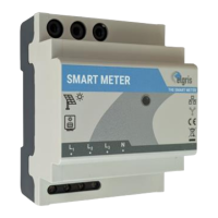
2.2 Device overview LAN
Before wiring the device, be sure that the voltage is switched off.
GRID/NETZ
LOAD/LAST
N
L3
Standard arrow
2 AT
Ethernet
RS-485
L1
L2
L3
N
L
K
K
L
GRID
LOAD
N
Ethernet
RS-485
2.3 Pin description LAN
Voltage
input
Pin
Description
Minimum
Maximum
1
Phase 1 voltage input
100 Vac
240 Vac
2
Phase 2 voltage input
100 Vac
240 Vac
3
Phase 3 voltage input
100 Vac
240 Vac
4
Neutral input of voltage
0 Vac
Power input
5
K input current transformer L1
0 Aac
5 Aac
6
L input current transformer L1
0 Aac
5 Aac
7
K input current transformer L2
0 Aac
5 Aac
8
L input current transformer L2
0 Aac
5 Aac
9
K input current transformer L3
0 Aac
5 Aac
10
L input current transformer L3
0 Aac
5 Aac
Dipswitc
h
1
IP address selection
OFF = DHCP
ON = static
2
System frequency
OFF = 50 Hz
ON = 60 Hz
3
Single or Three phase
OFF = Three phase
ON = Single phase
4
Internal use only
OFF = Default