13 - EN EWHT800LX
English
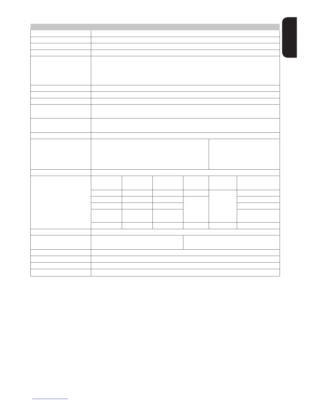
TECHNICAL DATA
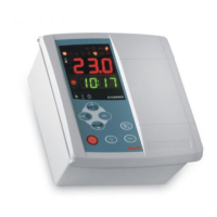
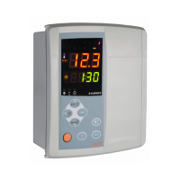
Dimensions front 210x245mm, depth 90mm
wall mounting (centre distance of holes A-B 181.0 mm; holes C-D 196.5 mm. See Mechanical Installation paragraph)
Connections • removable screw terminals for serial port RS-485, digital and analogue inputs
• removable screw or FASTON terminals for power supply and digital relay outputs (see Wiring Diagrams)
internal housing for door lock disconnecting switch, remote control switch, etc.
WARNING: do not exceed the amperage limits specied on the door lock disconnector markings
Operating temperature -5°C...+50°C
Operating and storage humidity
10..90% RH non-condensing
Display range • –50…110 °C (NTC) / -55...150°C (PTC) without decimal point, on display with 3 digits + sign
Analogue Inputs • 4 NTC inputs . PTC selectable by parameter H00
• 1 current input 4...20mA
4 voltage-free digital inputs congurable by parameters H11...H14
Relay outputs
• OUT1 output SPST 1/2HP 8(4)A 250Va
• OUT2 output SPST 1/2HP 8(4)A 250Va
• OUT3 output SPST 1/2HP 8(4)A 250Va
• OUT4 output SPST 2HP 12(12)A 250Va
• OUT5 output SPST 1HP 8(8)A 250Va
• OUT6 output SPDT 1/2HP 8(4)A 250Va
• OUT7 output SPDT 1HP 8(8)A 250Va
• OUT8 output SPST 1HP 8(8)A 250Va
Analogue Output 1 congurable analogue output
Analogue Output Table
Type Start of
scale range
Full scale
range
Resolution Accuracy Permissible
PWM - - 1% e.o.s.
±1% e.o.s.
4...20mA 4 20 500 Ohm
0-10V 0 10 55mA minimum load
resistance 180 Ohm
Buzzer only on models where this is provided
Serials • 1 TTL port for connection to Copy Card
• 1 TTL port for connection to TelevisSystem
• 1 RS-485 serial port for connection to Televis
System
(use with optional plug-in module)
better than 0.5% of end of scale +1 digit
NTC, PTC: 0,1 °C full range • 4...20mA : 1 digit (ndt = 0) / 0.1 digit (ndt=1)
Power draw 15W
Power supply
Important! Make sure the machine is switched off before working on the electrical connections.
The instrument is equipped with:
• Removable screw terminals: for connecting electric cables of 2.5 mm
2
maximum cross-sec-
tion (one wire per terminal in the case of power connections): for the capacity of the terminals, see the label
on the instrument. The relay outputs are voltage free: they are indicated on the board with the letters COM for
Common, NO for Normally Open and NC for Normally Closed contact. When current exceeds 8A on relay out-
puts, 2 x 2.5mm
2
cables (2 fastons) must be run out for each individual contact to ensure the temperature of the
cables does not exceed 85°C.
• Fastons: single row of fastons in series. Do not exceed the maximum permitted current; for
higher loads, use a contactor with sufcient power capacity. Make sure that power supply is of the correct voltage
for the instrument.
Probes have no connection polarity and can be extended using a normal bipolar cable (note that the extension
of the probes inuences the instrument's electromagnetic compatibility (EMC): take great care with the wiring).
Probe cables, power supply cables and the TTL serial cables should be routed separately from power cables.
WARNINGS
 Loading...