39
40
41
0...20mA
4..20mA
GND
39
40
41
0...10V PWM
10V 55mA
485+
GND
485-
RS-485
RS-485
Keyboard
Copy
Card
EWHT800 LX
14
15
16
Pb3
Pb4
Pb2
Pb1
DI4 DI3 DI2 DI1
Power
Supply
100...240V
17
18
19
20 21
22
23
24
31
32
39
40
41
45
46
47 51
52
53
Analogue
Output - AO
Pb5
TTL
25
26
27
28
29
30
64
65
66
67
68
69
70
71
54
55
56
57 59
60
61
62
Removable
Terminals
OUT8 OUT7 OUT6 OUT5 OUT4 OUT3 OUT2 OUT1
H28 H27 H26 H25 H24 H23 H22 H21
Relais
Parameters
Default configuration
LINE
NEUTRAL
Faston
2 3 4 5
10
11
12
13
8 9
AUX 1
AUX 1
RS485 connection to
TelevisSystem available
with optional plug-in
module only
Copy
Card
Bus
Adapter
RS 485
TTL
AUX 2
AUX 2
+
+
-
-
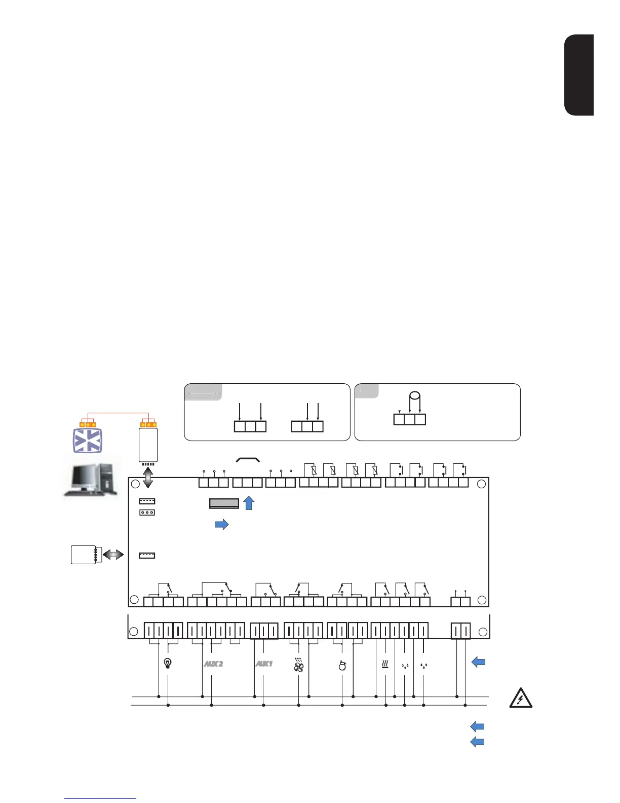
ELECTRICAL CONNECTIONS
Output relay (default settings)
•OUT1 = Dehumidication
•OUT2 = Humidication
•OUT3 = Heating
•OUT4 = Compressor
•OUT5 = Evaporator fan
•OUT6 = Auxiliary 1 (ventilation fans)
•OUT7 = Auxiliary 2 (destratication fans)
•OUT8 = Light
Probe inputs (default settings)
• Pb1 = NTC cold room probe
• Pb2 = NTC defrost end probe
• Pb3 = NTC (de)stratication probe
• Pb4 = NTC condenser fan probe
• Pb5 = Humidity probe / pressure transducer
4...20mA
To switch between NTC/PTC probe types use pa-
rameter H00. SWITCH OFF AND RESTART THE
INSTRUMENT after making the change
Digital Inputs (default settings)
• D.I.1 = Door switch
• D.I.2 = Alarm
• D.I.3 = Low pressure
• D.I.4 = High pressure
Analogue Output (default settings)
• AO = 0-10V for piloting external fan module
Serials
• TTL for connection to Copy Card
• TTL for connection to TelevisSystem
• RS485 available ONLY with optional Plugin
module for connection to TelevisSystem.
Important! Make sure the machine is switched
off before working on the electrical connections.
• Removable screw terminals: electric cables
of 2.5 mm
2
maximum cross-section (one wire
per terminal in the case of power connections).
• FASTONS: single row of fastons in series.
 Loading...