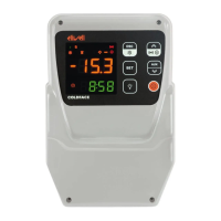
EWPlus + ECPlus
7/8
PAR. DESCRIPTION RANGE M.U. EWPlus 961 EWPlus 971 EWPlus 974 LEVEL
HAL (!)
Maximum temperature alarm. Temperature value (intended either as distance from
Setpoint or as an absolute value based on Att) which, if exceeded in an upward direction,
triggers the activation of the alarm signal. See "Max/Min Temperature Alarms".
LAL ... 320 °C/°F 50.0 50.0 50.0 1&2
LAL (!)
Minimum temperature alarm. Temperature value (intended as distance from the set point
or as an absolute value based on Att) which, when exceeded downwards, triggers the
activation of the alarm signal. See "Max/Min Temperature Alarms".
-67.0 ... HAL °C/°F -50.0 -50.0 -50.0 1&2
PAO
(!)
Alarm exclusion time after instrument switch on, after a power failure.
This parameter refers to high/low temperature alarms only.
0 ... 10 ore 0 0 0 2
dAO Temperature alarm exclusion time after defrost. 0 ... 999 min 0 0 0 2
OAO
Alarm signaling delay after digital input disabling (door close).
This parameter refers to high/low temperature alarms only.
0 ... 10 ore 0 0 0 2
tdO Alarm activation delay time open door. 0 ... 250 min 0 0 0 2
tAO
Temperature alarm signal delay time.
This parameter refers to high/low temperature alarms only.
0 ... 250 min 0 0 0 1&2
dAt
Alarm for defrosting ended due to time out.
n = alarm deactivated; y = alarm activated.
n/y flag n n 2
rLO External alarm locks controllers. n = does not lock; y = locks. n/y flag n n n 2
LIGHTS & DIGITAL INPUTS ('Lit' folder)
dOd
Enable utility switch-off on activation of door switch. 0= disabled;
1= disables fans; 2= disables compressor; 3= disables fans and compressor.
0/1/2/3 num 0 0 0 2
dAd Activation delay for digital input. 0 ... 255 min 0 0 0 2
ENERGY SAVING ('EnS' folder)
OSP Offset on setpoint. -30.0 ... 30.0 °C/°F 1.0 1.0 1.0 2
DISPLAY ('diS' folder)
LOC
LOCk. Setpoint change shutdown. There is still the possibility to enter into parameters
programming and modify these, including the status of this parameter to permit keyboard
shutdown. n = no; y = yes.
n/y flag n n n 1&2
PS1
PAssword 1.
When enabled (PS1 ≠ 0), this is the access key to level 1 parameters (User).
0...250 num 0 0 0 1&2
PS2
PAssword 2.
When enabled (PS2 ≠ 0), this is the access key to level 2 parameters (Installer).
0...250 num 15 15 15 2
ndt Display with decimal point. n = no (integers only); y = yes. n/y flag y y y 2
CA1
Calibration 1.
Positive or negative temperature value added to the value read by Pb1.
This sum is used both for the temperature displayed and for regulation.
-12.0 ... 12.0 °C/°F 0.0 0.0 0.0 1&2
CA2
Calibration 2.
Positive or negative temperature value added to the value read by Pb2.
This sum is used both for the temperature displayed and for regulation.
-12.0 ... 12.0 °C/°F 0.0 0.0 1&2
ddL
Display mode during defrost.
0 = display the temperature read by Pb1;
1 = locks the reading on the temperature value read by Pb1 when defrosting starts, and
until the next time the SEt value is reached;
2 = displays the label deF during defrosting, and until the next time the SEt value is
reached.
0/1/2 num 1 1 1 1&2
dro
Select °C or °F for displaying the temperature read by probes. 0 = °C, 1 = °F.
NOTE: switching between °C and °F or vice-versa DOES NOT modify the SEt,
diF values, etc. (e.g. Setpoint=10°C becomes 10°F).
0/1 num 0 0 0 2
ddd
Selection of type of value to be displayed. 0 = Setpoint;
1 = probe Pb1; 2 = probe Pb2; 3 = not used; 4 = Display "ON"; 5 = not used.
0 ... 5 num 1 1 1 2
ddE
Selection of value to display on ECHO (ECPlus). 0 = Disabled (not present);
1 = probe Pb1; 2 = probe Pb2; 3 = not used; 4 = Setpoint.
0 ... 4 num 1 1 1 2
CONFIGURATION ('CnF' folder) - NOTE: the instrument must be switched off and then on again each time folder CnF parameter configuration is modified to prevent
any malfunction of the configuration and/or current timer operations.
H08
Stand-by operating mode.
0 = display switch off; the loads are active and the device reactivates the display to signal
any alarms;
1 = display switch off, loads and alarms stopped;
2 = display with OFF label, loads and alarms stopped.
0/1/2 num 2 2 2 2
H11
Configuration of digital input 1/polarity (D.I.1).
0 = disabled; ± 1 = defrost; ± 2 = reduced SET; ± 3 = AUX;
± 4 = door switch; ± 5 = external alarm; ± 6 = stand-by (ON-OFF);
± 7 = not used; ± 8 = deep cooling; ± 9 = not used; ±10 = not used.
NOTE: - the '+' sign indicates that the input is active if the contact is closed
- the '-' sign indicates that the input is active if the contact is open
-10 ... 10 num 0 0 0 2
H21
Configurability of digital output 1 (A).
0 = disabled; 1 = compressor; 2 = defrost;
3 = fans; 4 = alarm; 5 = AUX;
6 = Stand-by; 7 = not used; 8 = condenser fan change rotation;
9 = Heater; 10 = defrost on 2nd evaporator; 11 = 2nd compressor.
0 ... 11 num 1 1 1 2
H22 Configurability of digital output 2 (B). Same as H21. 0 ... 11 num 2 2 2
H23 Configurability of digital output 3 (C). Same as H21. 0 ... 11 num 3 2
H32
Configurability of DOWN key.
0 = disabled; 1 = defrost;
2 = AUX; 3 = reduced SET;
4 = Stand-by; 5 = deep cooling; 6 = not used.
0 ... 6 num 0 0 0 2
H42 Evaporator probe present (Pb2). n= not present; y= present. n/y flag y y 1&2
reL reLease firmware. Device version: read-only parameter. / / / / / 1&2
tAb tAble of parameters. Reserved: read-only parameter. / / / / / 1&2
 Loading...
