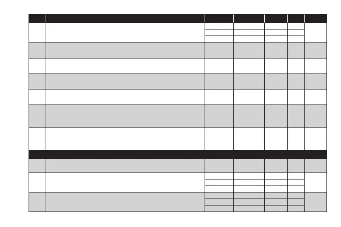
PAR. DESCRIPTION MODEL RANGE VALUE M.U. LEVEL
LA1
Minimum temperature alarm on OUT1.
(See ‘Max/Min temperature alarms’)
NTC/PTC -150.0...HA1 -50.0 °C/°F
User/InstPT100-Tc -328...HA1 -199.9 °C/°F
V/I -150...HA1 -150 num
dn1
Switch-on delay. The indicated time must elapse between the request for
activation of the controller 1 relay and switch-on. 0 = not active.
ALL 0...250 0 min Inst
dO1
Delay time after switching off. The indicated time must elapse between
deactivation of the controller 1 relay and the next switch-on. 0 = not active.
ALL 0...250 0 min Inst
di1
Delay between switch-ons. The indicated time must elapse between two
consecutive switch-ons of regulator 1. 0 = not active.
ALL 0...250 0 min Inst
dE1
Switch-off delay. The indicated time must elapse between the request for
deactivation of the controller 1 relay and switch-off. 0 = not active.
ALL 0...250 0 min Inst
On1
Controller 1 switch-on time in the event of faulty probe.
if On1=1 and OF1=0, the controller remains on;
if On1=1 and OF1>0, the controller operates in Duty Cycle mode.
ALL 0...250 0 min Inst
OF1
Controller 1 switch-off time in the event of faulty probe.
if OF1=1 and On1=0, the controller remains off;
if OF1=1 and On1>0, the controller operates in Duty Cycle mode.
ALL 0...250 1 min Inst
CONTROLLER 2 (folder ‘rE2’)
HC2
This sets the controller 2 operating mode.
H (0) = Hot; C (1) = Cold.
ALL H/C H flag Inst
OS2 Temperature value to be added to SP2 if reduced set enabled
NTC/PTC -30.0...30.0 0.0 °C/°F
InstPT100-Tc -30.0...30.0 0.0 °C/°F
V/I -30...30 0 num
db2
Operating band 2.
(See ‘ON/OFF regulation diagram’)
NTC/PTC 0.0...30.0 1.0 °C/°F
InstPT100-Tc 0.0...30.0 1.0 °C/°F
V/I 0...30 1 num