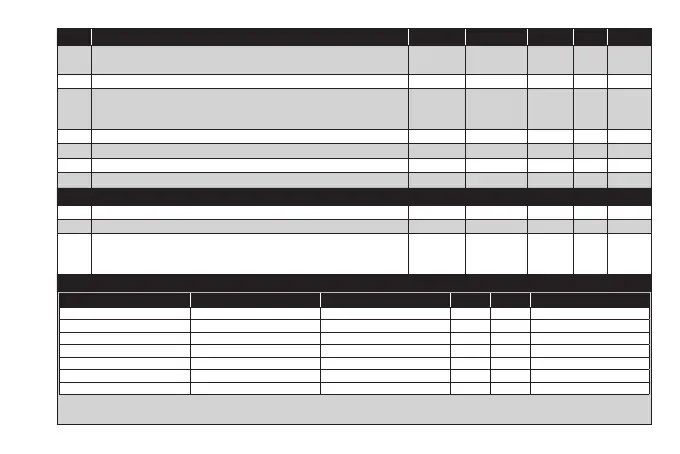
PAR. DESCRIPTION MODEL RANGE VALUE M.U. LEVEL
H21
Configuration of Digital Output1 (OUT1). 0 = disabled; 1 =
on-off (controller 1)
2 =
on-off (controller 2)
; 3 = Alarm; 4 = Cyclic; 5 = Aux/Light; 6 = Stand-by.
ALL 0...6 1 num Inst
H22 Configuration of Digital Output2 (OUT2). Same as H21. ALL 0...6 1 num Inst
H31
Configuration of UP key.
0 = disabled; 1 = SOFT START; 2 = Offset setpoint; 3 = Outputs stopped;
4 = Periodic cycle; 5 = AUX output; 6 = Stand-by; 7 = not used.
ALL 0...7 0 num Inst
H32 Configuration of DOWN key. Same as H31. ALL 0...7 0 num Inst
H33 Configuration of ESC key. Same as H31. ALL 0...7 6 num Inst
rEL firmware version. Device software release: read-only parameter. ALL / / / User/Inst
tAb Parameters table. Reserved: read-only parameter. ALL / / / User
COPY CARD (folder ‘FPr’)
UL Upload. Transfer of programming parameters from instrument to Copy Card. ALL / / / Inst
dL Download. Transfer of programming parameters from Copy Card to instrument. ALL / / / Inst
Fr
Format. Cancels all data entered in the Copy Card.
IMPORTANT: If parameter Fr (Copy Card formatting) is used, the data entered
in the card will be permanently lost. This operation cannot be reversed.
ALL / / / Inst
FUNCTIONS (folder ‘FnC’)
Function Function label ACTIVE Function label NOT ACTIVE D.I. KEY Alarm signaling
Soft start SOn SOF 1 1 Flashing icon
Reduced setpoint OSP SP 2 2 ON Icon
Actuations block bOn bOF 3 3 ON Icon
Periodic cycle Con CoF 4 4 ON Icon
AUX AOn AOF 5 5 ON Icon
Stand-by On OF 6 6 ON Icon
Alarm acknowledgement tAL tAL 7 7 ON Icon
NOTES: - to modify the status of a given function, press the ‘set’ key
- If the instrument is switched off, the function labels will return to the default status