V/I MODEL
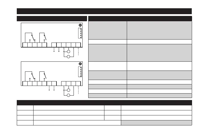
CONNECTIONS
INPUT/OUTPUT CHARACTERISTICS
Display range:
-199...199 (ndt = n)
-199.9...199.9 (ndt = y)
-1999...1999 (ndt = int)
on display with 3½ digits + sign
Digital input 1 digital voltage free input
Analogue input
1 V/I (0-1V, 0-5V, 0-10V, 0...20mA, 4...20mA)
(selectable by parameter H00)
Maximum load: - current = 100 Ω
- voltage = 20 kΩ
Serial
TTL for connection to Copy Card or Televis/
Modbus remote control systems
Digital outputs
OUT1: 1 SPDT relay 8(4)A 250 Va
OUT2: 1 SPST relay 8(4)A 250 Va
Buzzer output only on models where this is provided
Measurement range -1999 ... 1999
Accuracy better than 0.5% of end of scale +1 digit
Resolution 1 or 0.1 digit according to settings
V/I - 12V, 12-24V
+12V
I
V
+ +−
Supply
OUT1 OUT2
1 2 3 4 5 7 8 9 10 11 12
V/I - 24V, 115V, 230V
+12V
I
V
+ +−
Supply
OUT1 OUT2
1 2 3 4 5 7 9 10 11 126
TERMINALS
1-2-3 regulator relay OUT1 *7-8
Power supply 12V
a/c
and 12-24V
a/
12-36V
c
.
4-5 regulator relay OUT2 *9-10-12 Voltage input (9=GND; 10=”+”; 12=12V)
*6-7
Power supply 24V
a
, 115V
a
and 230V
a
.
*9-11-12 Current input (9=GND; 11=”+”; 12=12V)
A TTL input for Copy Card and TelevisSystem connection * depends on model