10/14
NOTE: At level 1 the folders will only display all the level 1 parameters. At level 2 the folders will only display all the
level 2 parameters.
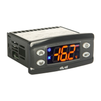
IWP 760 LX Fan Condenser
HdL Maximum value that can be displayed
-50.0...302
140.0
2 °C/°F
PAR. DESCRIPTION
RANGE DEFAULT LEVEL** U.M.
Display - diS label
ddL Display during defrosting:
0= displays temperature read by thermostat con-
trol probe
1= displays temperature read entering defrost
cycle until set point is reached
2= displays “deF” label during defrosting until
set point is reached (or when Ldd expires)
0/1/2 1 1 flag
Ldd Time out for unlocking display (with ddL=2) if
defrosting lasts too long
0...255
0
1 min
dro (8) Select °C or °F to display temperature:
0= °C
1= °F
0/1
0
1 flag
ddd Value to be displayed:
0 = Set point
1 = probe 1 (thermostat control)
2 = probe 2 (evaporator)
3 = probe 3 (display)
0/1/2/3
1
2 num
H11 (9) Configuration of digital input/polarity D.I.1:
0= disabled 1 = defrost
2 = reduced set point 3 = auxiliary
4 = door switch 5= external alarm
6= not used 7= stand-by (On/Off)
8= maintenance request 9= min pressure switch
10= max pressure switch 11= general pressure switch
12= preheating 13= evaporator fan forcing
14= light relay ON 15= Frame Heater relay ON
16= enables/disables nAd functions
-16...16
4
2 num
H08 Stand-by operating mode
0= only display is switched off;
1= display on and controllers disabled;
2= display off and controllers disabled
3= OFF appears on display and all controllers
are disabled
0/1/2/3
2
2 num
H00 Selects probe, PTC or NTC
0= PTC
1= NTC
0/1
1
1 flag
H02 Quick activation time for functions with configured
buttons. Not possible for aux
(time expected = 1 second)
0...15
5
2 sec
H06 Button/input aux/door switch light active when
instrument is off
n/y
y
2 flag
Configuration- CnF label
H12 (9) Configurability of digital input/polarity D.I.2
(Same as H11)
-16...16
2
2 num
H13 (9) Configurability of digital input/polarity D.I.3
(Same as H11)
-16...16
12
2 num
H14 (9) Configurability of digital input/polarity D.I.4
(Same as H11)
-16...16
11
2 num
H21 Digital output 1 configurability:
0= disabled 1= compressor
2= defrosting 3 = fans
4 = alarm 5= auxiliary
6= stand-by 7= light
8= buzzer 9= defrost on 2nd evaporator
10= 2nd compressor 11= Frame Heater
12= condenser fans (see page 4/14 Condenser Fan Controller)
0...12
1
2 num
CA2 Temperature value to be added to that read by
probe 2 as specified by parameter CA
-12.0...12.0
0
1 °C/°F
CA Intervention of offset on display, thermostat con-
trol or both:
0 = only modifies the temperature displayed
1 = adds to the temperature used by controllers
not the temperature displayed that remains unchanged.
2= adds to temperature displayed that is also
used by controllers.
0/1/2
2
2 num
LdL Minimum value that can be displayed
-55.0...140
-50.0
2 °C/°F
140.0 2
1 1
0 1
0 1
1 2
4 2
3 2
1 1
5 2
1 2
2 2
12 2
11 2
1 2
0 1
2 2
-50.0 2
CUSTOM SETTINGS
DEFAULT - LEVEL
 Loading...