© 1999 ELKA-Torantriebe GmbH & Co. Betriebs KG page ES 25, ES 30, ES 40
3
3. Installation
a) When you make the concrete foundation lay enough cable or a plastic duct for the cable you need.
The foundation must be at least 800 mm deep with a horizontal surface 500 x 550 mm.
b) Using the template you can, either incorporate bolts in the foundation, or drill holes in the hardened
concrete for heavy-duty plugs. The door side of the template must be toward the road which the barrier
will be closing.
c) As an alternative 2 "U"-profile clamping-irons are delivered with the barrier. This gives more flexibility in
positioning the fastening points and allows the barrier to be lined up exactly as required.
d) Secure the barrier on the foundation.
e) Connect the boom holder to the shaft.
Tighten all screws, the top ones first with 35 Nm.
The enclosed nuts and bolts are a predetermined breaking point
and should only be replaced with the same sorts.
(Bolt M 8 x 50 ISO 4762 12.9, Nut hexagonal M 8-8 ISO 4032)
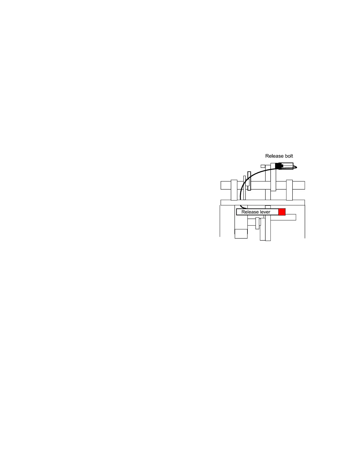
f) Emergency release by current failure etc. Pull the lever with the
red end which is behind the access panel. The boom can then be
raised manually. To engage the boom again pull the lever and
pull the boom down, the release bolt will then lock at the
appropriate position.
The controller is switched off until the boom is locked at the
operating position.
g) Mount the boom before doing a test run. If necessary adjust the limit switches and the stoppers.
h) The logic board MO 62 is connected to the terminals (X1) in the barrier and to the microswitches in the head.
All electrical connections should be carried out at the front of the terminals (X1). The barrier is ready for use
when delivered. The running time and a ‘stay open’ time of 5 seconds are stored in an eeprom. You only
require the programming mode if the time to stay open (when automatic closure is being used) is to be
altered, or when a logic card is replaced.
Switch off the mains supply before altering the operating mode dip switches!
Pull out the fuse-holder where mains supply is connected to X1
4. Logic card MO 62