EZWSMD*1A EZWSM8*1A EZWSM8*2A LZWSMD*1A LZWSM8*1A LZWSM8*2A
Page 4
2000000485 (Rev. A - 01/22)
INSTALLATION INSTRUCTIONS
1. Install mounting frame and chiller shelf. See mounting frame instructions.
2. Mount the upper BF panel to the mounting frame: Mount upper panel by aligning holes in the hinge brackets with holes in the mounting frame
(three places). Mount with adequate size screws (not provided). Close the door and verify that the lock brackets on the side and bottom of the
panel align with the slots on the mounting frame. Also verify that the panel is hanging high enough that it covers the top of the mounting frame.
3. Mount the lower Chiller panel to the mounting frame: Mount the lower panel by aligning holes in the hinge brackets with holes in the mounting
frame (three places). Mount with adequate size screws (not provided). Close the door and verify that the lock brackets on the side of the panel
align with the slots on the mounting frame. If adjustments need to be made, open the doors to make adjustments. Open panels for adjustments.
Loosen the (4) screws on the hinges of each panel and adjust accordingly and then re-tighten screws. Close and Lock the top panel in place
using two set screws (provided) on the side of the panel, and a ¼ x 20 bolt through the front of the panel into the nut in the frame.
4. Attach drain: Attach the drain ttings to drain tube. Attach elbow to p-trap and cut waste tube to required length using plumbing hardware and
trap as a guide.
5. Install remote chiller: See chiller instructions. Remove protective caps from water lines on chiller.
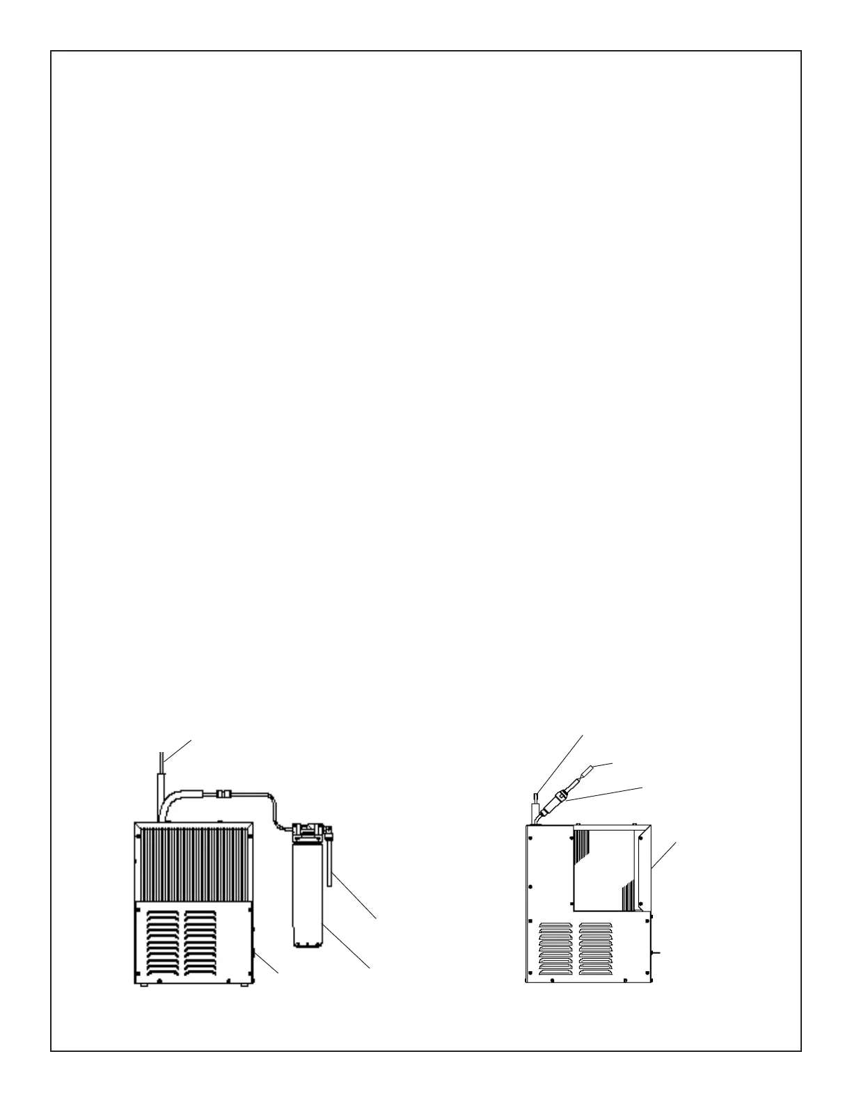
TO BOTTLE FILLER
CHILLER
INLET
PLUMBING DIAGRAM
Fig. 5
EWF3000 WATERSENTRY PLUS FILTER INSTALLATION (Fig. 5): (Filter units only. For non-ltered units proceed to step 15)
NOTICE: Do not use water that is microbiologically unsafe or of unknown quality without adequate disinfection before or after the system.
CAUTION: If supply pressure will ever exceed 100 psi, install a pressure regulator set to 100 psi or below.
DO NOT ATTACH HOT WATER LINE TO FILTER HEAD.
Filter kits must be installed in compliance with all state and local laws and regulations governing the installation and use of this product.
Maximum inlet water temperature: 100°F (38°C).
See lter instructions for lter head assembly.
6. Connect Filter Kit: Using the lter mounting bracket and screws supplied, mount lter head using the (3) screw holes on the side of the chiller.
Allow enough room under the lter head for the installation and removal of the lter cartridge (13” minimum). To make tube connections on the
lter head, loosen locknut. Push the tube end past both O-rings to a positive stop in the lter head recess - approx. 1". Screw the locknut hand
tight to seal (See Fig. 5). Ends of tubing must be cut square and free of burrs and sharp ends that could cut or nick the O-rings.
7. Connect lter water outlet: Connect the outlet of the lter head to the inlet of the chiller using the ¼” O.D. poly tubing and ¼” elbow
union supplied.
8. Place Chiller on Shelf: When mounting unit in a cavity or behind a wall maintain a minimum space of 4” (102mm) on top, sides and a
depth of 12” (305mm).
9. Connect bottle lter line: Connect water line from BF station by inserting the ¼” O.D. poly tubing into union on the chiller outlet.
10. Remove Chiller Front panel: Remove the (10) screws securing chiller front panel.
11. Connect electrical to chiller: Make sure power supply is identical in voltage, cycle and phase to that specied on cooler serial plate. Never wire
Compressor directly to the power supply. While chiller panel is off, adjust cold control if needed.
12. Replace chiller panel: Using the (10) screws re-secure the panel.
13. Plug bottle ller into wall box receptacle.
14. Install a shut-off valve: Install a shut-off valve and union connection to building water supply (valve and union not provided). Connect 3/8”
shut-off valve to 3/8” copper tubing inlet of lter head.
15. Install lter cartridge: remove lter from carton, remove protective cap, and attach lter to lter head by rmly inserting into head and rotating
lter clockwise.
16. Go to step 18.
FILTER
CHILLER
TO BOTTLE FILLER
STRAINER
NON FILTEREDFILTERED
INLET
 Loading...