B-66 IntelliTouch/SecureTouch Guide
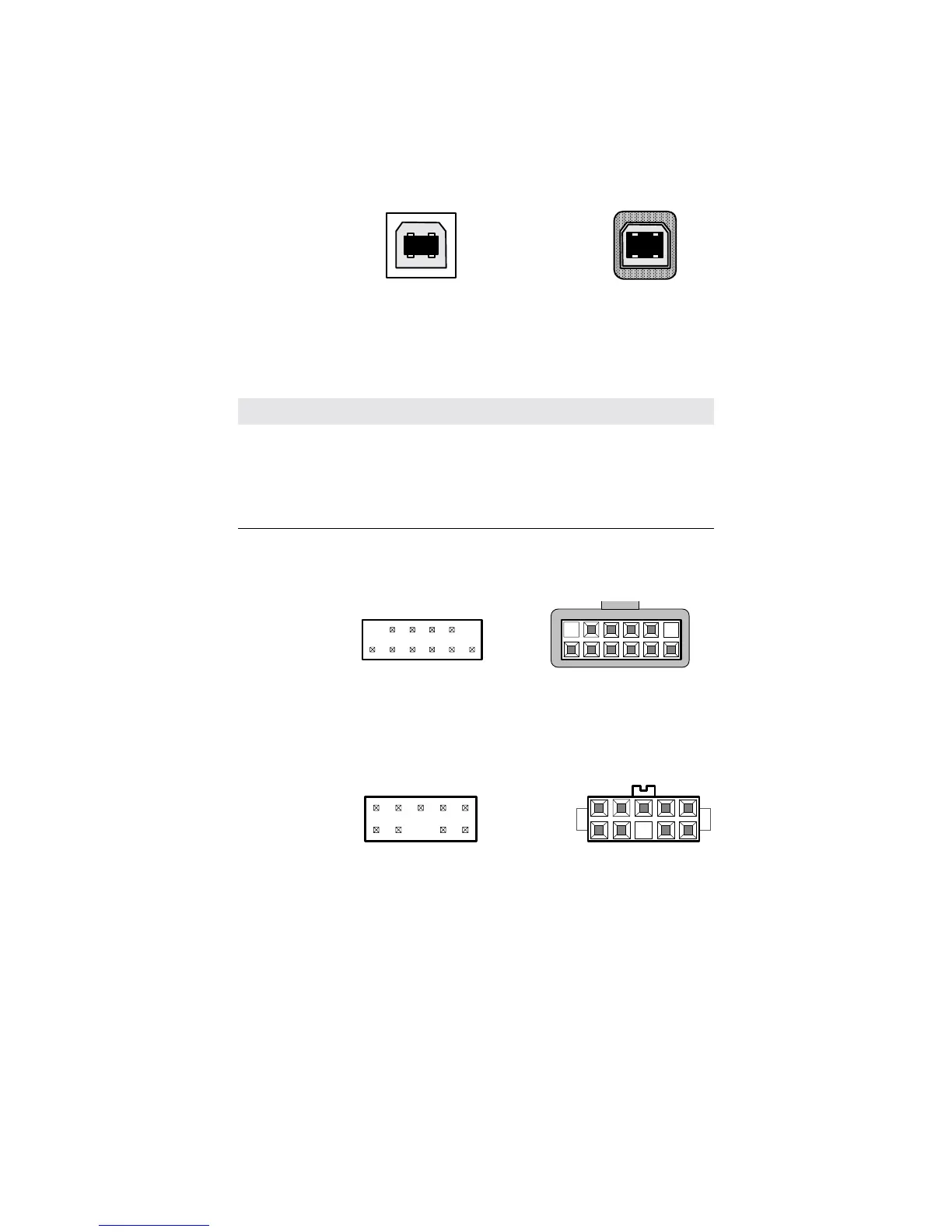
Figure B.1
P2, USB board-mounted header and cable-mounted plug.
Table B.1
USB connector pin numbers and signal names
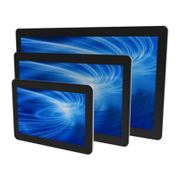
Figure B.2
Pin diagram for touchscreen connector, P3, as viewed from connector
mating surfaces.
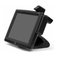
Figure B.3
Power connector board-mounted header and cable mounted-plug.
21
VBUS
D-
D+
GND
board-mounted
receptacle
cable-mounted
plug
43
1
4
2
3
P2 pin number Signal name Standard wire color
1VBUSRED
2D-WHITE
3 D+ GREEN
4 GND BLACK
shell shield drain wire
Board mounted
header
Cable applied
plug
1
2
11
12
1
2
11
12
header
Cable applied
plug
1
2
1
2
9
10
9
10
Board mounted