B-74 IntelliTouch/SecureTouch Guide
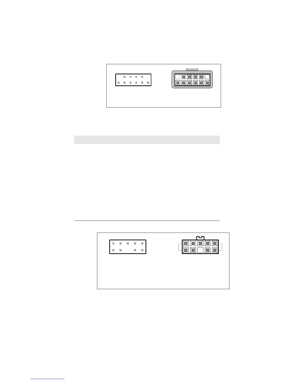
Figure B.9
Pin diagram for touchscreen connector, P3, as viewed from connector
mating surfaces.
Table B.6
Touchscreen connector, P3, pins and signal names
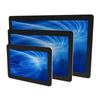
Figure B.10
Pin diagram for power connector, P4, as viewed from connector mating
surfaces
Board mounted
header
Cable applied
plug
1
2
11
12
1
2
11
12
Signal name P3 pin Signal function
Chassis 1 frame ground for cable shield
none 2 connector key
Y rcv + 3
Y xmt + 4
Y rcv - 5
Y xmt - 6 analog ground
analog gnd 7 analog ground
X xmt - 8 analog ground
X rcv - 9
X xmt + 10
X rcv + 11
none 12 connector key
header
Cable applied
plug
1
2
1
2
9
10
9
10
Board mounted