Manual R1140-X0-ST-EN Release: 1.06 © Elotech GmbH Page 4/24
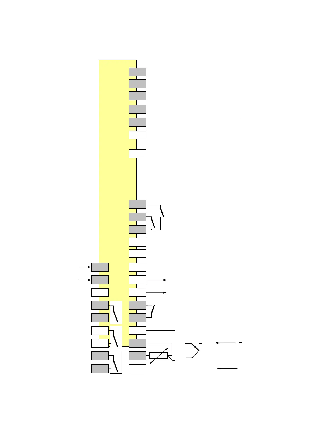
4. R1140-10: Connection diagram
CAN Profibus RS232-C RS485 0/20mA
90 GND GND GND GND
91 VP +5V RxD out RxD in
92 CNTR TxD in RxD out
93 H RxTxP TxD out A TxD out
94 L RxTxN RxD in B TxD in
95 The bus-lines have to be conncted with specific
terminating resistors.
Please take care to the detailled interface- or
96 data transfer descriptions.
Note: Only in the specific interface-technologie trained
personnel following the regulations may do the
interface-connections. It is essential, that one has
well experience in installing a device with interface.
70
K3: external, potential-free contact
71
K2: external, potential-free contact
72
73
74
L / DC - 1 75
Power Supply
N / DC+ 2 76 + OUT 4
bistable 0/18VDC or 0/4…20mA or 0/2…10V
3 77 - OUT 4
OUT 1 4 78
Control output K1: external, potential-free contact
5 79
OUT2 6 80
Control output
or Alarm A2 7 81
OUT 3 8 82 TC 0-20mA
Alarm A3 4-20mA
9 83 RTD/ Pt100 +
2-wire connection:
jumper between termonals 81 and 80
It is not permitted to connect the grounds of the sensor- and bist. voltage-outputs with each other.