Application and Operation
3 Application and Operation
3.1 System
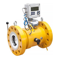
The ultrasonic flow meter comprises of the following main parts as listed
below and seen in Figure 3-1. The flow cell (in yellow) is the part of the
ultrasonic flow meter that is mounted in the piping system. All other
components are mounted on the flow cell.
Figure 3-1: Example of an Elster Ultrasonic Gas Flow Meter
Temperature
Sensor
(rear side)
 Loading...