Operating & Maintenance Instructions 33
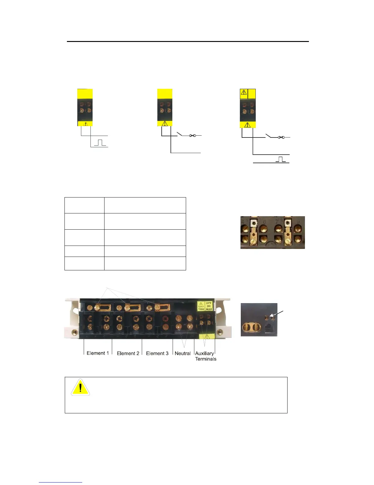
Voltage Links shown in open position (whole current meters only)
Auxiliary Configurations 3phase 4 wire meters
Note: Connections available for 3 phase 3 wire meters are shown in brackets
Floating SO Two Rate (No SO) SO and Two Rate
Terminal Numbering
1
2
3
Element 1 - Line in
- Voltage terminal
- Line out
4
5
6
Element 2 - Line In
- Voltage Terminal
- Line Out
7
8
9
Element 3 - Line In
- Voltage Terminal
- Line Out
10
12
Neutral In
Neutral Out
Auxiliary See Auxiliary configurations above
Auxiliary Voltage Terminals
(Optional)
Terminal Block
Auxiliary Terminals
Note: These diagrams are examples only.
WARNING
Meters must be wired as shown on the diagram fitted under the meter terminal cover.
Figure 5 - Terminal Arrangements
+
-
20
21
27V DC
MAX
13
2A (max)
15
A, B or C
(A or C)
Neutral
(B)
230V
+
13
2A (max)
20
A, B or C
Neutral
27V
DC
MAXTOU


 To Next Page