Operating & Maintenance Instructions 39
high
Logic
levels
low
Start
bit
Serial word
Data bits
Stop
bit
Stop
bit
high
Infra-red
intensity
low
Start
bit
IR frame
Data bits
Bit
time
Pulse
width
0 0 0 1 0 1
1111
0 1 0 1 0 1 1 1 0 1
1 3 5 7
24 68
(real data bits in bold)
high
Output
Current
low
Start
bit
Serial output word
Data bits
Stop
bit
0 0 0 1 0 1
1111
1 3 5 7
24 68
APPENDIX A – IRDA DATA FORMATS
A1 Introduction
The A1100 uses the OBIS (OBject Identification System to IEC 62056-61) data identifiers to
transmit data via its IrDA Port and serial data port. The port continuously transmits the meters
registration, security and status data.
The IrDA baud rate is configurable at manufacture to 2400, 4800 or 9600 baud. A PC or a PDA with
an IrDA optical probe can be used to read the IrDA data.
A2 IrDA Output Message
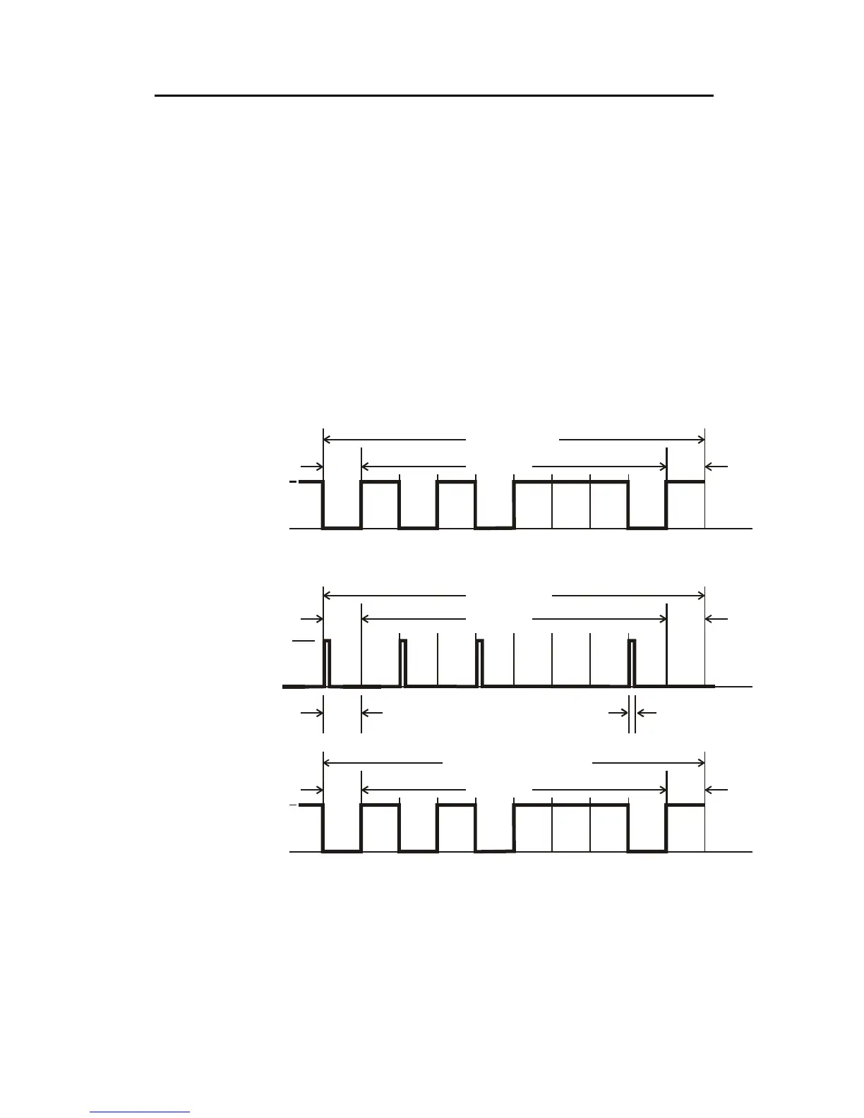
The port transmits registration, security and status data once every 4 seconds. The format of each data
word is shown below:
Serial
Word
Format
IrDA
Output
Serial
Data
Output
Note: each IR frame only carries one nibble of data.
For the IrDA output a pulse of approximately 5μs is output on the occurrence of a logic ‘1’ to ‘0’
transition. No output is present when a logic ‘1’ is transmitted.
For the serial data output the bit period is set by the baud rate.


 To Next Page