Temp. Sensor cable 1
Block1
- + + - + - + -
Block4Block3
Cable lugs mounted
upside down
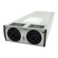
Common Battery
Cables (+)
Electrical Installation Power is OFF!
Carry out the following: (Refer to the next chapters “Location of
Components…” and “Connections…” or to the system’s specific drawings)
CAUTION: The cable lengths must be long enough (service loop) to allow opening the
Minipack drawer shelf.
9 Make the system completely voltage free
o Switch OFF or remove all load fuses (MCB1, MCBx), battery
fuses (Fb1, Fbx) and the AC supply fuses, in external fuse
boards
10 AC Connections
o Check AC configuration: the external AC supply consists of 3
single phase mains feed and earth (PE)
o Connect the AC Earth wires (PE) to the terminals X5:1-2 (PE)
o Connect the AC input cables to the terminals X5:3-4, 5-6, 7-8.
Cable and terminal block labeling are to correspond
o If the 3ph AC Input Connection Kit, part 228898 or 238394 is
used, follow the kit’s guide instead
11 DC Connections ⎯ Load Circuits
o DC Earth (TE); check that the common DC Output Rail is
connected to “Telecom Earth” (TE) at only one place (at the
cabinet , cable X7A, or at a central distribution point)
o For each DC load, connect one of the cables to the common DC
output terminal, and the other to terminal X6B:F1, F2, etc.
12 DC Connections ⎯ Alarm & Signal Circuits
o Refer to your system’s connection drawings and configuration, or
to the “Appendix, Alarms & Monitoring” section, terminal
blocks X1, X2A and or X2B.
o Terminate Alarm Circuit cables to the relay output terminals
o Terminate Signal Circuit cables to the digital input/output
terminals
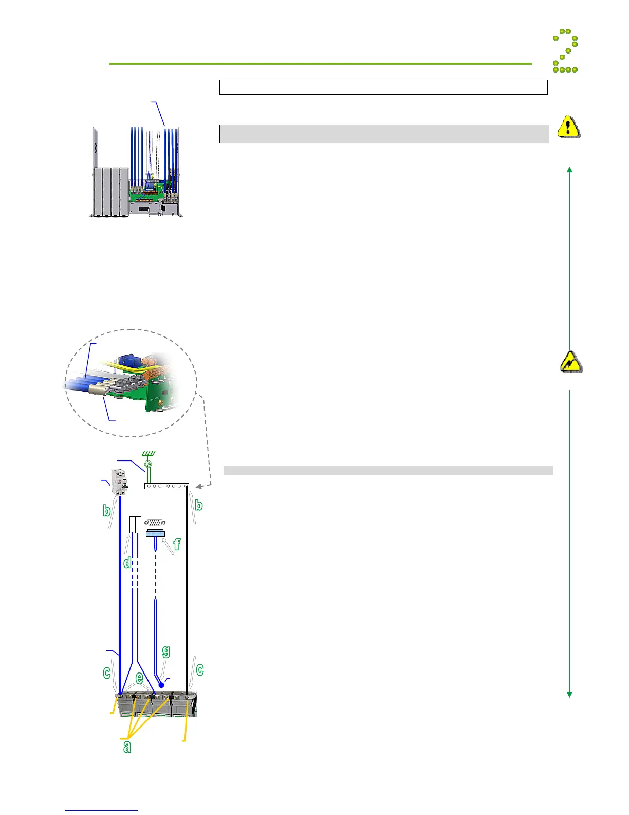
13 DC Connections ⎯ Battery Cables
CAREFUL! Use correct polarity.
For 48V systems using the battery symmetry mid-point
measurement, refer to the figure in this page.
For other measurement methods, refer to the Battery Symmetry
Connections chapters in this guide’s Appendix section.
For each battery shelf:
CAUTION: Mount cable lugs upside down on the (+) battery cables
a Mount 3 intercell links to connect in series 4 battery blocks
b-c Connect battery cables to fuses (Fb1, Fb2, etc.) and
Common Battery (X7A) and to the battery shelf’s outer
terminals; (+) and (-)
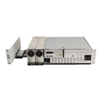
d-e Connect battery symmetry cables, if applicable, to the input
terminals, and to the center terminal of the battery string
(+) and to the -48V outer terminal. Deviation from factory
settings requires Symmetry reconfiguration via PowerSuite
f-g Connect the temperature sensor cable, if applicable, to the
D-Sub plug or input terminal, and fix the temperature
sensor (at the end of the cable) to a suitable place in the
middle of the installed battery bank
Electric
shock
Device
hazard
 Loading...