Quick Start Guide Minipack PS System 356808.103, 1v2-2008-10
23
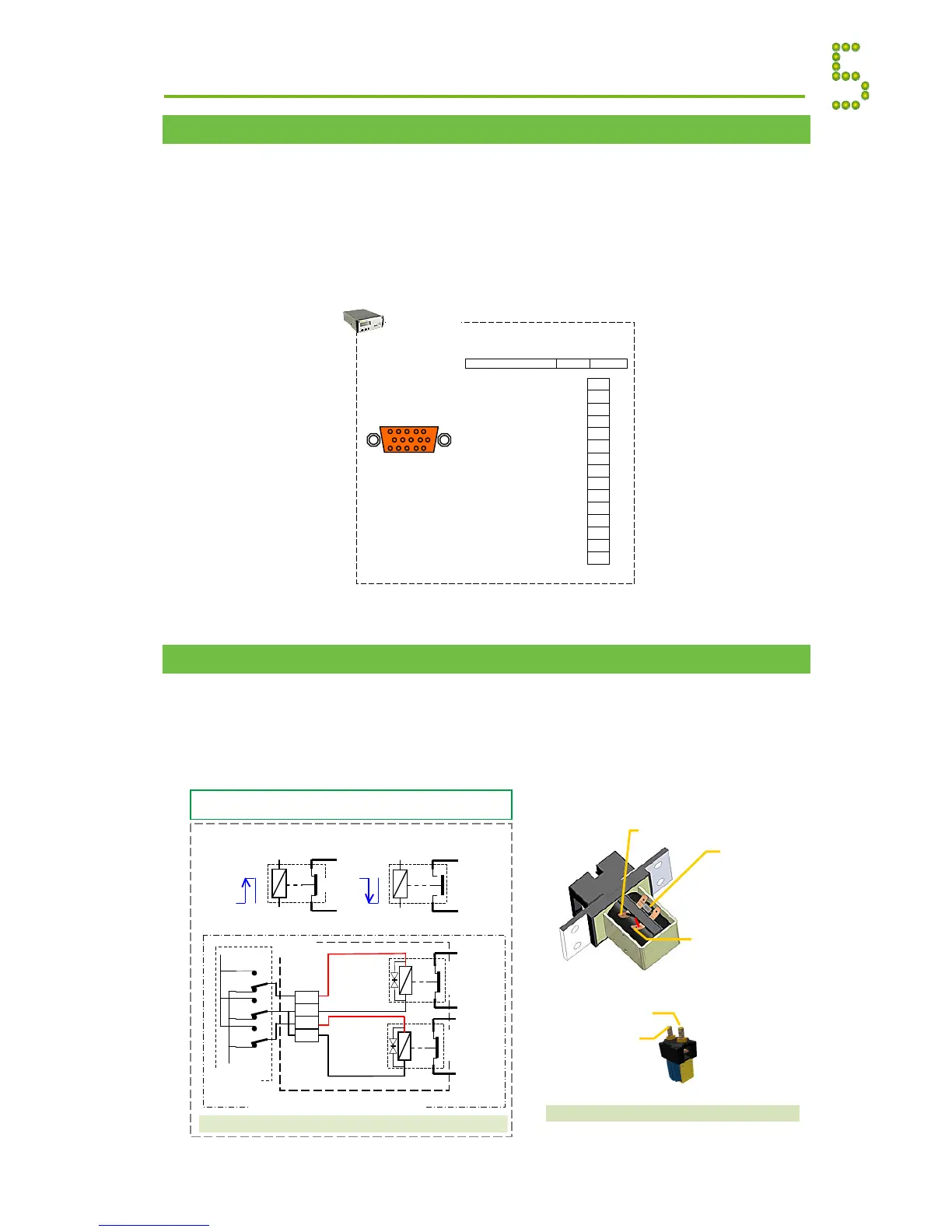
System Interface Card ~ Terminals & Pin-out
Minipack systems are shipped from factory with the CON5 signals already connected.
Some of the Smartpack controller’s internal system signals are accessible on D-Sub connector
CON5, on the controller’s rear panel.
Using a standard 15 pins D-Sub cable, the signals on CON5 are routed to the Minipack system’s
main circuit board. See the figure in this section for an overview of the signals on CON5,
LVD Latching Contactors Connections
Minipack systems’ LVBD and LVLD functionality (Low Voltage Battery Disconnect; LV Load
Disconnect) is implemented by the Smartpack controlling magnetically latching contactors.
The coil of latching contactors is not energized in any state. They change state from open to close,
or vice versa, when a reversed pulse is applied to the coil.
System
Connections
CON5
15 pins D-Sub (female)
LVD1A +/
15
FUNCTION SIGNALPIN-OUT
5 1
15 11
CON5
(female; orange)
Smartpack
controller
Latching Contactors, LVD1 & LVD2
Correct Use of Latching Contactors (example)
latching contactor changes state only when a
reversed pulse voltage is applied to its coil
+ Pulse
ON
- Pulse
OFF
10
8
9
X:*****
+
—
LVD1A
LVD2A
LVD Common
Smartpack
controller
Minipack PS System (internal)
11
LVD Common
Latching
Contactor
LVD2
Y
X
Latching
Contactor
LVD1
Y
X
Minipack
Main PCB
Internal Connections Appendix
 Loading...