larm Circuit 6
X2A
4
3
2
1
5
9
8
7
6
10
+
−
+
−
+
−
+
−
Digital Input 3
Digital Input 4
Digital Input 5
Digital Input 6
(To external equipment) (From external equipment)
NO
COM
NC
NO
COM
NC
NO
COM
NC
NO
COM
NC
Relay 3
Fuse Alarm
Load & Battery
Relay 5
Low Battery Alarm
Relay 6
Rectifier Alarm
Relay 4
High Battery Alarm
To Smartpack,
CON2
14
13
12
11
15
16
17
18
19
20
X2B
Card Art. 218473
To CON2
1
10
X2A
11
20
X2B
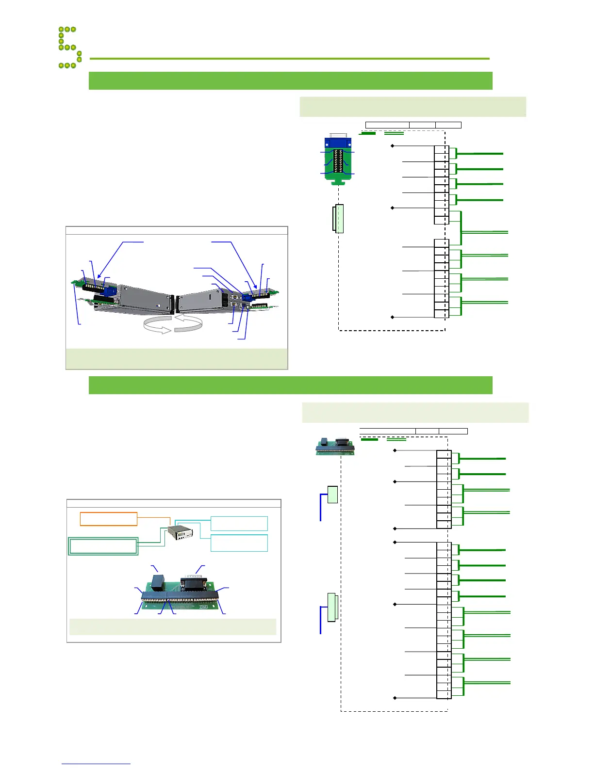
The figure shows the position of the relay contacts when the PS
system is in alarm mode of operation; the relay coils are then de-
energized (fail-safe mode). The relay outputs are preprogrammed
from factory (Factory Settings).
Alarm Interface Card, Extended ~ Terminals & Pin-out
Additional alarm and digital input monitoring
signals are accessible from the Smartpack
controller’s rear panel, on D-Sub connector
CON2 (4 outputs & 4 inputs).
Using the Alarm Interface Card, Extended (Art.
218473) plugged to Smartpack’s CON2, you can
make the signals on CON2 accessible on terminal
blocks X2A and X2B. The figures show the
card’s pin-out location and terminal block
connections.
Alarm Interface Card, External ~ Terminals & Pin-out
Instead of the piggy-back cards 218470 and
218473, you can use the Alarm Interface Card
(Art. 105954) and two interface cables, to make
the signals on CON1 & 2 accessible at any
suitable location inside your cabinet.
The figures show the card’s pin-out location and
terminal block connections.
Appendix Alarms & Monitoring
larm Circuit 6
4
3
2
1
5
9
8
7
6
10
14
13
12
11
15
X:**
16
17
18
19
20
+
−
+
−
+
−
+
−
NO
COM
NC
NO
COM
NC
NO
COM
NC
NO
COM
NC
Digital Input 3
Digital Input 4
Digital Input 5
Digital Input 6
Relay 3
Fuse Alarm
Load & Battery
Relay 5
Low Battery Alarm
Relay 6
Rectifier Alarm
(To external equipment) (From external equipment)
Card Art.105954
To Smartpack,
CON2
To Smartpack,
CON1
Relay 4
High Battery Alarm
Terminals & Pin-out Location
Alarm Outputs & Digital Inputs Card, Art. 105954
(or Art. 200916 when X** and CON2A are not mounted)
CON2A CON1
larm Outputs & Digital
Inputs Card, Art. 105954
System Connections
Card, Art. 200625
Smartpack
Battery Connections
Card, Art. 200576
Battery Connections
Card, Art. 200576
CON1A
CON2A
CON2
CON1
The figure shows the position of the relay contacts when the PS
system is in alarm mode of operation; the relay coils are then de-
energized (fail-safe mode). The relay outputs are preprogrammed
from factory (Factory Settings).
 Loading...