Quick Start Guide Minipack PS System 356808.103, 1v2-2008-10
14
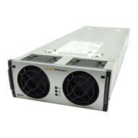
CAN Bus Termination
Minipack systems are shipped from factory
with the CAN bus already terminated with
120Ω resistors.
To ensure a correct bus communication and
avoid data reflection, you must always
terminate the CAN bus with two 120Ω
resistors, one at each end of the line (60Ω
bus impedance). The figure shows a
Minipack system with its controller
communicating with the rectifiers via the
CAN bus.
CAN Bus Addressing
All rectifiers, Smartpack controllers and other control units connected to the Eltek Valere’s CAN
bus must have a unique address or ID number. The control system’s master controller assigns
automatically the rectifiers’ addresses (software assignment). The controller registers the
rectifiers’ ID numbers – or CAN bus address (01, 02 ...) – together with their Serial Numbers.
The control system’s controllers and control units use DIP switches for configuring their unique
CAN bus ID number (hardware assignment).
You can address a maximum of 14 control units of each type – Smartpack controllers, Smartnode
units, Battery Monitors, Load Monitors, etc. – to the control system’s CAN bus. See table below:
Number of nodes 1 2 3 4 5 6 7 8 9 10 11 12 13 14 15 16
Smartpack controllers 1 2 3 4 5 6 7 8 9 10 11 12 13 14
15 16
<-- ID #
Smartnodes 17 18 19 20 21 22 23 24 25 26 27 28 29 30
31 32
<-- ID #
Battery Monitor CAN nodes 33 34 35 36 37 38 39 40 41 42 43 44 45 46
47 48
<-- ID #
Load Monitor CAN nodes 49 50 51 52 53 54 55 56 57 58 59 60 61 62
63 64
<-- ID #
65 66 67 68 69 70 71 72 73 74 75 76 77 78 79 80
<-- ID #
I/O Monitor CAN nodes 81 82 83 84 85 86 87 88 89 90 91 92 93 94
95 96
<-- ID #
Mains Monitor nodes 97 98 99 100 101 102 103 104 105 106 107 108 109 110
111 112
<-- ID #
ID numbers formatted in italics (column 15 and 16 and range 65-78) are not available due to
software constraints. For DIP switch configuration, refer to chapter “CAN Bus Nodes”, page 24.
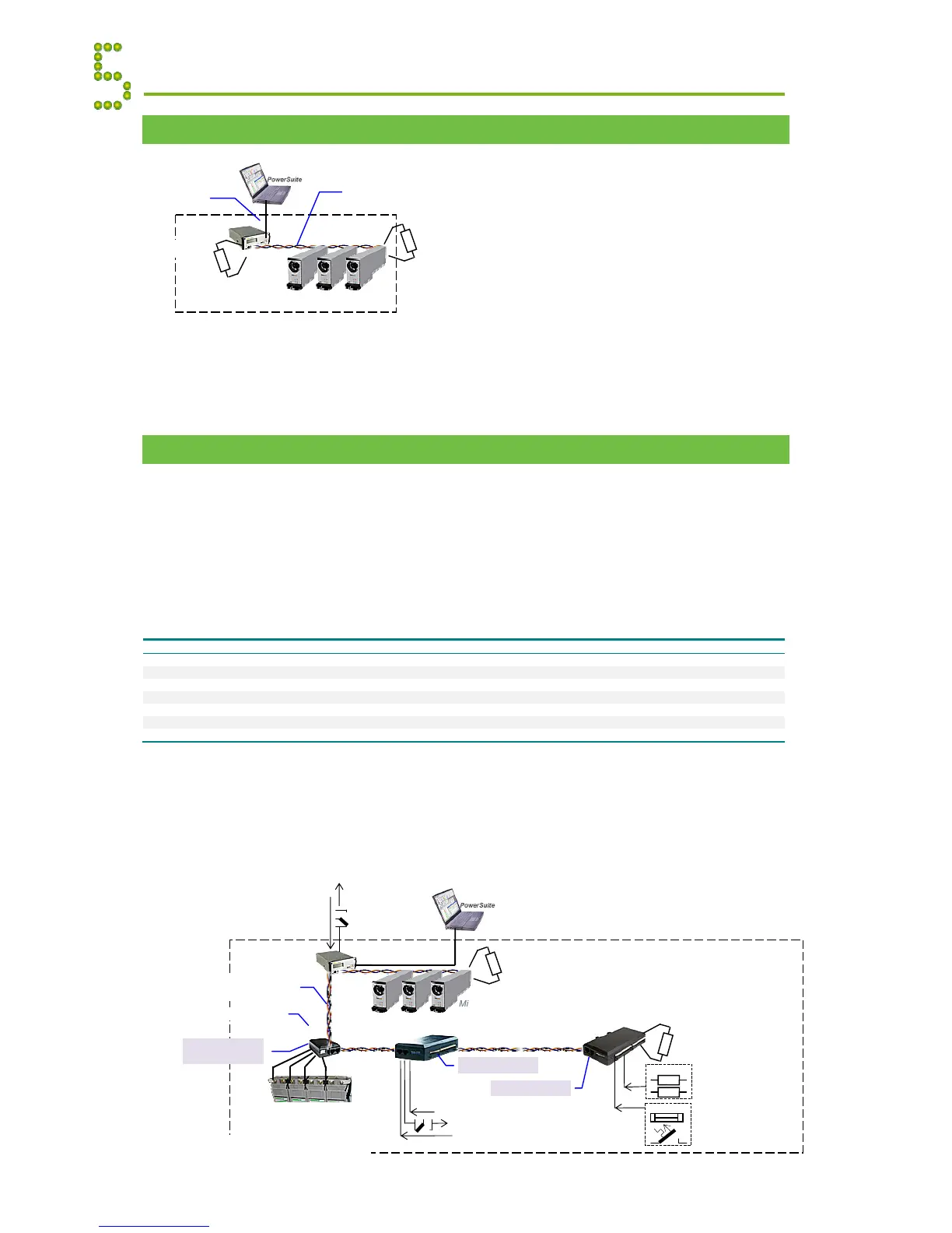
The figure shows a Minipack DC power system expanded with 3 CAN nodes to implement
additional digital inputs, relay outputs or similar functionality.
Appendix Communication
 Loading...