Quick Start Guide Minipack PS System 356808.103, 1v2-2008-10
26
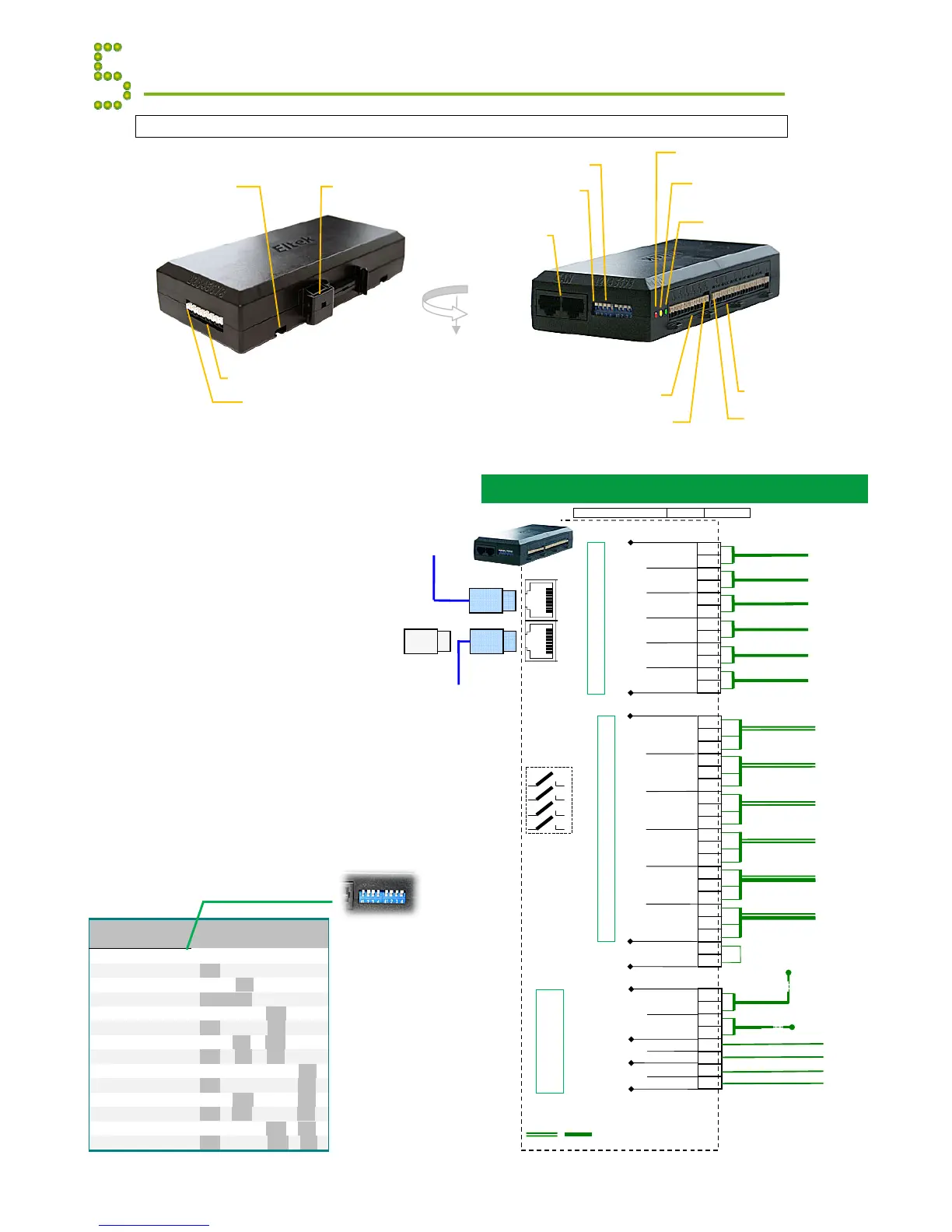
I/O Monitor CAN Node
The I/O Monitor CAN Bus Node
enables you to decentralize and
increase the number of input
monitoring and output controlling
signals in your Smartpack based DC
power supply system. Also, it
monitors and controls the
compartment temperature inside fan-
cooled outdoor cabinets.
Read also the “Installation Guide
I/O Monitor CAN Node”, document
351503.033.
Appendix CAN Bus Nodes
RJ45 CAN bus termination plug, if the I/O
Monitor is the last node in the CAN bus
(Customer Connections)
1.
 Loading...